
Abstract
A simple device will be presented that can be installed into a “theft-prone” vehicle (caravan, RV, boat etc.) to detect and respond to unlawful movement of the vehicle like theft etc. It can be seen as a starting point for own further developments and is composed from off-the-shelf modules only:
- STM32F4 microcontroller (“Blackpill Board”)
- GPS/NMEA decoder module
- SIM800-L GSM module
- OLED display (128 x 64 pixels)
- 3.3V voltage regulator
When irregular movement of the vehicle is detected, the system reports the current position by sending an SMS to a defined mobile phone number repeatedly. As the system relies on a GSM network, usage on boats is limited to a distance within a range of about 10 miles from coast as there are no GSM repeaters out on the sea.
Layout and methods
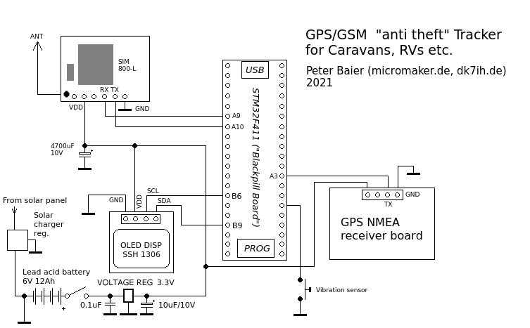
This “anti-theft” systems binds together the components mentioned before. The GPS/NMEA module and the SIM800-L GPS module communicate via USART (TX and RX lines only) with the STM32F4 microcontroller. Here USART1 (SIM800-L) and USART2 (GPS/NMEA-module) in the MCU are used. The GPS-board reports the system’s current position by transmitting a standard NMEA-string (“$GPGLL”) which contains geolocation data and the current time stamp. This string is stored inside microcontroller and is updated once per second.
A vibration sensor is activated as soon as relevant movement of the vehicle is detected. The mircocontroller then starts the GSM transmitter/receiver module (SIM800-L). This module generates an SMS containing the current geolocation. This message is transmitted to a given mobile phone number repeatedly so real-time tracking is possible.
Power supply considerations
Power supply either is crucial for the readiness of the device but also the SIM800-L module is some how “tricky” concerning DC power.
The device can be powered by a lead-acid rechargeable battery with 6V nominal voltage. A charger for lead batteries is connected to a solar panel on top of the vehicle. The 6V are regulated by 2 step-down regulators:
- 3.3V for the GPS-module, the OLED display and the MCU
- 4V for the SIM800-L GPS TX/RX module
Important: SIM800-L needs a very stable power supply that is able to cope with high peak current (about 2 amps max. but only for short periods). Thus a massive capacitor (C= 4700uF, Umax. = 10V) has been paralleled to the power supply close to the module. A “Gold cap” mini battery also is possible. If peak current is not sufficiently stable, the module will lose connection to the GSM grid which will be indicated by a flashing LED onboard the module. When a connection is established, the onbaord LED only flashes once every 3 seconds.
Wiring the modules
Connections between the four modules (STM32F4-MCU, GPS, GSM and OLED) are very simple:
- MCU PB9 -> OLED SDA, PB6 OLED SCK
- GPS TX -> MCU PA3 (USART2)
- MCU PA9 -> SIM800-L TX, PA10 -> SIM800-L RX
On an experimental board the wiring should be easily understood (click on picture on the right to see full size view):
Sensors
![]() The sensor technique to activate the GPS tracking in this basic version only consists of a vibration sensor. It closes a circuit that pulls an MCU pin (A0) to GND as soon as relevant vibration occurs.
The sensor technique to activate the GPS tracking in this basic version only consists of a vibration sensor. It closes a circuit that pulls an MCU pin (A0) to GND as soon as relevant vibration occurs.
Schematic
“Talking” to the SIM-module
To send an SMS with SIM800-L a USART connection (usually in standard format 9600-8-N-1) has to be set up. Data coding is done by the well-known “AT” commands used with the telephone modems in the 90s and beyond.
The first command that is applied when an SMS in standard text format shall be transmitted is
AT+CMGF=1
which is answered by the SIM module with an “OK” message. This puts the module into the SMS text mode.
Next the recipient’s telephone number has to be transferred:
AT+CMGS=”004917112345678″
After that the prompt “>” is received which means that the module is ready for taking the message text now:
Hello world! <ALT Z>
<ALT Z> (0x1A) is the control code to indicate the end of the message text.
The last command is used to sign the message reference number allocated to the SMS text message. Usually an arbitrary number can used for our purposes.
+CMGS: 1
After this the message will be sent via the network to its designated recipient.
Software
The software is, as usual, coded in Embedded C for ARM-Cortex microcontrollers. You can download source code from my Github repo.