
On this resource you can find drivers supporting the AVR/ATmega-Series by ATMEL (now Microchip) for a lots of peripheral devices. All code is written for the ATmega32 but can easily be converted for similar MCU models. There are display drivers for various DOT-matrix and graphical displays. Also oscillators (DDS and CLK) will be covered and sensors soon are to be added. So, stay tuned! 🙂
Driver code is written in Embedded C for AVR microcontrollers (using GNU AVR C Compiler suite). No “Arduino”, sorry!
Display drivers
LCD 16×2 (DOT-Matrix)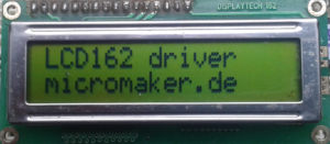
ST7920 (Monochrome graphical display)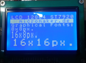
ILI9341 (Graphical display – SPI version)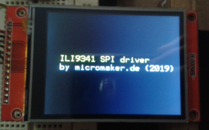
ST7735 (Graphical display)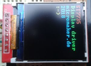
Nokia 5110 (Graphical display, monochrome)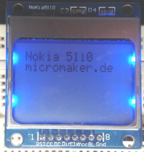
OLED SH1106 (monochrome graphical OLED)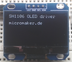
OLED SSD1306 (monochrome graphical OLED)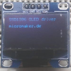
Oscillators (DDS & Clock)
AD9951 (400MHz max. clock, 14 bit DAC) Direct Digital Synthesizer
(The code also contains function for clock multiplying)
AD9834 (75MHz max. clock, 10 bit DAC)
AD9835 (50max. clock, 10 bit DAC)
AD9850 (125MHz mac. clock, 10 bit DAC)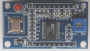
Si5351 (programmable clock oscillator 8..160MHz)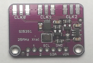
Sensors, Controls etc.
BMP180 Pressure and temperature
The 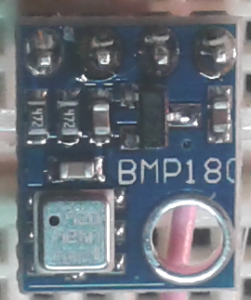 demonstration code hands over the alphanumeric data for air pressure and ambient temperature to a data connection using UART. A terminal program (like gtkterm for Linux oder HyperTerm for Windows) must be connected via a level shifter (MAX232 or equivalent) to pin PD0 of the Atmega32 MCU.
Paramaters are:
- 9600Bd.
- 8 databits
- No parity
- 1 stopbit
Rotary encoder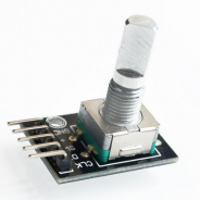
Detecting the direction of a rotating encoder.
There are 3 version of the code. Version 2 is more simple than Version 1 concerning INT-routine. If it does not work from scratch, try to change the encoder pins A and B since there is only 1 interrupt triggering pin. If it is the “wrong” one only one direction will be detected!
V3 in addition uses Timer1 as counter for Milliseconds and resets LEDs 1s after the last took place.
Miscellaneous modules
MCP4725 (Digital to analog converter, DAC)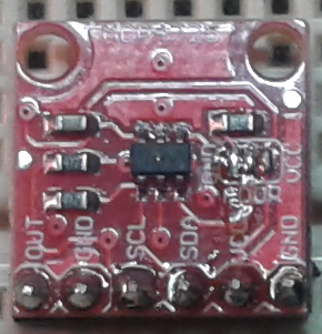
The MCP4725 DAC is used as a simple sine wave generator to demonstrate an easy to understand application.
24C65 External EEPROM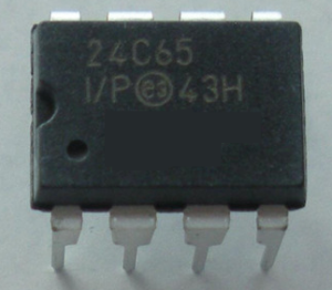
This example writes numerical data into the EEPROM and reads it subsequently. If both values are the same a green LED flashes, if there is an error, a red LED is lit.
The green LED goes from VDD via a 100Ω resistor to PD0, the red LED to PD1 the same way.
LTC1257 DAC
As the MCP4725 the LTC1257 converts digital signals to analog values. The LTC1257 in contrast to the device mentioned before uses an SPI interface (3 wires). The demonstration code converts the output of a sine wave function into a voltage.