
0 Abstract
AD9850 is a widely used direct digital synthesizer (DDS) for output frequencies up to 40MHz. It can be driven in two modes, serial (SPI) and parallel. Both ways will be described in this article including schematics and software.
1 AD9850 technical outline
The DDS integrated circuit is in a 28 pin SMD package with the following pin outline.
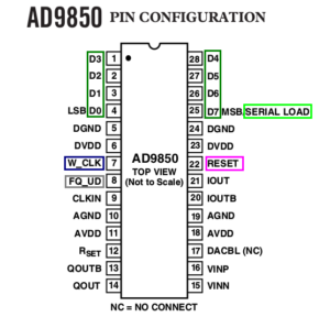
In parallel mode D7…D0 make up the data bus, in parallel mode D7 is the serial input pin.
In both modes (parallel or serial) 40 bytes of frequency data have to be transferred:
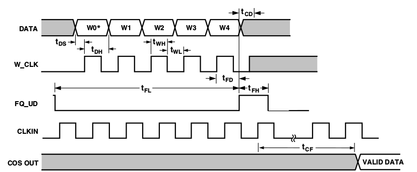
AD9850 parallel mode timing
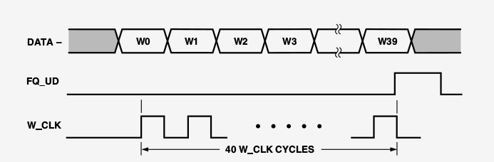
AD9850 serial mode timing
The FQ_UD line (frequency-update) and W_CLK line (clock signal) modes are the same in both types of operation. Thus there are only small variations in the two respective functions to control the DDS system:
The code for parallel data transfer:
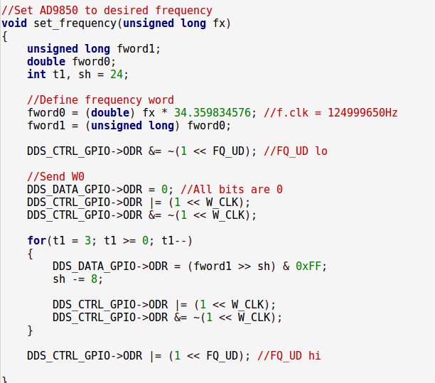
(Get code from my Github repo)
And here for serial mode:
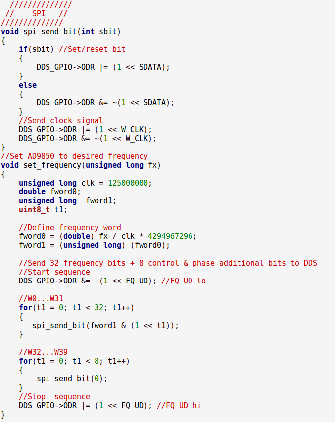
(Get code from my Github repo)
In the respective code examples all the defines and GPIO settings are also included. Software should run “out of the box”!
Thanks and see you soon!
By Peter Baier