
0 Abstract
Today’s lesson will cover a topic that the software developer will encounter sooner or later: The need to decode the signals from a rotary encoder. We will discuss that and deliver a simple and easy-to-use solution for this problem.
1 Theory behind a rotary encoder
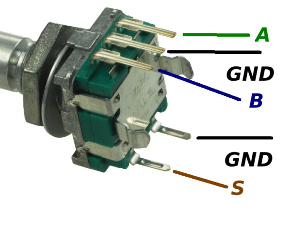
A rotary encoder is a set of two mechanical or optical switches driven by a rotating axle, a “shaft”. Both switches are connected to the same GND potential, thus these encoders have two outputs (usually called “A” and “”B”) and a share common ground (GND). Sometimes they also are equipped with an additional push button (S):
1.1 Function in brief
When the encoder is rotated, the two switches A and B change their status from “open” to “closed” with a certain phase delay bet ween outputs A and B:
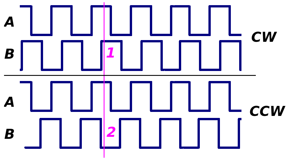
You can see from the picture that clockwise rotation (CW) is present when signal “A” is high and signal “B” presents a rising edge while signal “A” preserves its status (1). In contrast, when the shaft is turned counterclockwise (CCW), signal “A” is high again but “B” shows a falling edge (2). By decoding these two signals as a function of time you can clearly distinguish between CW and CCW rotation.
1.2 Reading the rotary encoder in software
Polling the two output lines of the encoder and subsequent decoding is one method to find out about rotor’s status but that wastes a large amount of processor time. The best way to get the rotation direction of this type of encoder is to use interrupts. Signal “A” triggers an interrupt and simultaneously signal “B” is measured.
For example you can trigger an interrupt when “A” represents a falling edge, meaning that it has been “high” right before, and signal “B” will not have changed its status yet. So you can clearly discern the direction of the rotating shaft.
2 Reading a rotary encoder with STM32F4
Due to the fact that these encoders are widely used in modern electronics, the STM32F4 has integrated functions to read out such devices. But we will use a different method, the well known one from AVRs. That means using something that is called “pin change interrupt”. This type of triggering interrupts also is available in the STM32 MCUs when you write a piece of code for it.
Step 1: Define the input ports and the interrupt
In this example we want to read out a rotary encoder that is connected to pin PB0 and PB1 of an STM32F411 on a “Black Pill”-board. To check if this example code works, 2 indicator LEDs for CW and CCW turing are needed. The are switched from PB14 and PB15 towards VDD wih a 560 ohm resistor.
We have to define ports first:
//////////////////////////////////////////////
//Rotary Encoder Setup
//////////////////////////////////////////////
//Set PB0, PB1 as input pins
RCC->AHB1ENR |= (1 << 1); //GPIOB power up
GPIOB->MODER &= ~((3 << (0 << 1))|(3 << (1 << 1))); //PB0 und PB1 for Input
GPIOB->PUPDR |= (1 << (0 << 1))|(1 << (1 << 1)); //Pullup PB0 und PB1
First we power up port GPIOB, second we set PB0 and PB1 as inputs by writing 0b11 (dec. 3) into the respective bits of the MODER register. Next step: We set pull-up resistors because the input pins must have some electrical potential to be decoded when pulled to ground or left open.
Interrupt programming
Now we enable the System Configuration Controller in APB2ENR register (Bit 14), which, among other functions, controls the interrupt mapping from GPIO pins to the desired interrupt sources.
RCC->APB2ENR |= (1 << 14); //Enable SYSCFG clock (APB2ENR: bit 14)
The next 3 steps are related directly to the interrupt function we are about to use. The first line involves the EXTI0 (external interrupt 0) mapped to PB0. This is an essential step we have to explain more detailed:
In the STM32F4 MCU external interrupts are organized in so called “lines”. There are 16 of them. The special thing, if you want to say so, for former AVR developers is that all pins having the same number of the various MCU ports share the same “line”. This means, for example, that PA0, PB0, PC0 etc. share the same multiplexed interrupt bus and therefore only one external pin of this set can be used to trigger an interrupt in the respective line. There is a minor exception from this rule (concerning PA5 iirc) but generally this rule sticks for the whole system of external interrupts.
To map a certain pin to an interrupt the EXTICR registers have been designed. In the reference manual you can find them defined beginning with page 291. There are 4 of them:
- EXTICR1 (called EXTICR[0] in CMSIS header file)
- EXTICR2 (called EXTICR[1] in CMSIS header file)
- EXTICR3 (called EXTICR[2] in CMSIS header file)
- EXTICR4 (called EXTICR[3] in CMSIS header file)
As you can see, once again the identifiers in STM32F4 software package are different from datasheet! So care must be taken!
As an example (and for our code here) we take a closer look on EXTICR1 (EXTICR[0]).
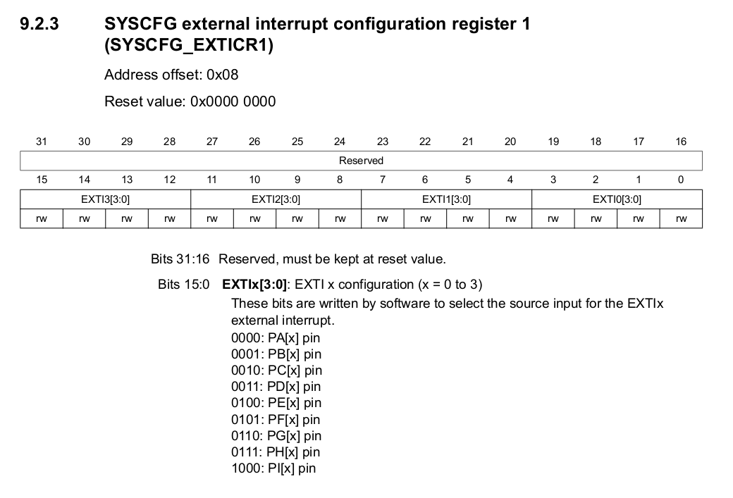
This definitely requires explanation: As we desire to use a pin with number “0” in its name, we have to use the group of pins (“line”) with “0” in the description. This line is represented in the EXTI0 bits [3:0] which also are bits 3:0 of this register. As it is PB0 we want to trigger the interrupt, we have to take the second line from the text block: 0001: PB[x]. This is because our “x” here is 0, so we write 0b0001 into the first 4 bits of this register:
SYSCFG->EXTICR[0] |= 0x0001; //Write 0001 to map PB0 to EXTI0
The remaining instructions define that we want to set up something in AVRs we would call “pin change interrupt”:
EXTI->RTSR |= 0x01; //Enable rising edge trigger on EXTI0
And last we have to exclude EXTI0 from the interrupts that are not fired on an event:
EXTI->IMR |= 0x01; //Mask EXTI0 in IMR register
The two remaining steps are defining interrupt priority and activating the interrupt:
NVIC_SetPriority(EXTI0_IRQn, 1); //Set Priority
Please note: Priority in interrupts is defined in a way, that the low numbers stand for high priority!
NVIC_EnableIRQ(EXTI0_IRQn); //Enable EXT0 IRQ from NVIC
So, again we are ready to go!
Last we have to set up the function that handles the interrupt once it is fired and deals with the pin data from the encoder: Declaration first
extern "C" void EXTI0_IRQHandler(void);
int16_t rotate = 0;
int16_t laststate = 0; //Last state of rotary encoder
and definition:
extern "C" void EXTI0_IRQHandler(void)
{
uint16_t state;

if(EXTI->PR & (1 << 0)) //Check first if the interrupt is triggered by EXTI0
{
    state = GPIOB->IDR & 0x03; //Read pins
    if(state & 1)
    {
        if(state & 2)
        {
            //Turn CW
            rotate = 1;
        }
        else
        {
            //Turn CCW
            rotate = -1;
        }
    }
    //Clear pending bit
    EXTI->PR = (1 << 0);
}
Here again we have to declare the function as ‘extern “C”‘ because when compiled under C++ settings the handler name will be altered by the compiler therefore the handler will not be recognized and your program will crash as soon as the interrupt is triggered.
Special: Using an external interrupt with higher numbers then “4”
For the STM32F4 MCU there are 7 interrupt handlers defined:
| Interrupt number | Handler | Description |
|---|---|---|
| EXTI0_IRQn | EXTI0_IRQHandler | Handler for pins connected to line 0 |
| EXTI1_IRQn | EXTI1_IRQHandler | Handler for pins connected to line 1 |
| EXTI2_IRQn | EXTI2_IRQHandler | Handler for pins connected to line 2 |
| EXTI3_IRQn | EXTI3_IRQHandler | Handler for pins connected to line 3 |
| EXTI4_IRQn | EXTI4_IRQHandler | Handler for pins connected to line 4 |
| EXTI9_5_IRQn | EXTI9_5_IRQHandler | Handler for pins connected to line 5 to 9 |
| EXTI15_10_IRQn | EXTI15_10_IRQHandler | Handler for pins connected to line 10 to 15 |
As you can see for interrupt numbers from 0 to 5 an individual function is defined. This means that the interrupt handler will only react to events on one specific pin: Pin 0, 1, 2, 3 or 4 independent from the port. Please keep in mind that all pins with the same number are “railed” to one interrupt handler!
With higher numbers than 4 two “collective” functions are given. The use of this sort of function I have demonstrated in a separate C file (rotary_encoder_PA11_PA12.c). With this example PA11 and PA12 are used as pins for the rotary encoder.
All rights reserved by Peter Baier, Bad Bergzabern, Germany (https://micromaker.de).