

(Onboard picture taken during flight, altitude approx. 60.000ft)
Abstract
An example for of an automatically working radio system controlled by a microcontroller will be discussed. The system supplies data transmission for telemetry purposes from a stratospheric balloon in order to record data with a ground station. It uses radio transmission on amateur radio frequencies. The system therefore requires that the operator is in possession of a valid amateur radio license. Furthermore, according to German regulations, a separate amateur radio call sign is required for the balloon transmitter, which from a legal point of view represents an independent radio station This permit is issued by the Federal Network Agency (BNetzA) on request.
“Space flight” took place on June 22nd 2016 from the schoolyard of the former school where the author worked as a science teacher then.
Basic outline
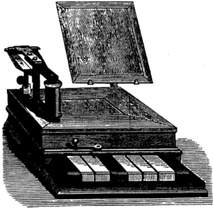
Historic teletype machine (Wikipedia)
This system uses Radio Teletyping (RTTY) for data transmission. This is due to the reason that radio amateurs have lots of equipment at hand to decode this type of signals. During flight a large number of radio operators tracked the balloon with their radio equipment because launch has been announced in advance in an internet forum for radio amateurs. So “real time tracking” was achieved not only by the receiving station in our school but by amateurs all over southwest Germany.
Radio Teletyping (RTTY)
RTTY encoding is a simple coding process for alphanumeric data to be transmitted via a radio link. It is a binary data transmission in which, similar to the ASCII code, data is encrypted with numerical values and then transmitted as a sequence of “0s” and “1s”. The code used is very widely known as the “Baudot code”. It was developed in 1870 by Frenchman Emile Baudot, who intended to develop a secure method for the (at that time still wired) transmission of text information. A method that could also be used by people who did not know Morse code.
The code according to Baudot is based on 5 bits and therefore allows a maximum of 2⁵ = 32 different symbols to be represented. In order to be able to transmit 26 letters, 10 digits as well as special and control characters, the character set was divided into two fractions, so that a total of 64 different characters can be transmitted. Toggling characters between the two levels requires 2 additional codes, so this number must be subtracted from the value of 64.
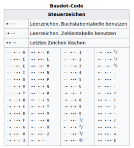
(Quelle: Wikipedia, frei verwendbar unter Creative Commons Attribution-ShareAlike)
If a “0” is transmitted as a bit, this logical state is called “Space”, while the “1” is called “Mark”. The characters “Mark” and “Space” are transmitted by radio using two different audio tones. The assignment of “Mark” to the high tone and “Space” to the low tone is not uniform, it may be necessary to convert the decoding software used accordingly. The two audible tones transmitted alternately are separated by a certain frequency amount, the so-called “shift”. This must be large enough that it can be reliably distinguished by a detection circuit even with low signal strengths and poor signal-to-noise (S/(S+N) ratio.
The tone spacing is therefore usually 170 or 850 Hz. Usually approx. 45 characters per second are transmitted (45.45 baud). The so-called 10-meter band of the amateur radio service was selected as the high-frequency transmission frequency for the module presented here.
What is Amateur Radio?
Amateur radio is a scientific experimental radio service and requires radio amateurs to take an amateur radio license test at a government agency before they are allowed to start transmitting. The frequency range used for this project between 28 and 29.7 MHz is in the so called “HF” (high frequency) region, which is defined as the frequency spectrum between 3 and 30MHz. It has a relatively low free space attenuation and, and with the current low level of solar activity in 2016, it is free of radio signals that could come from a great distance and might interfere with the operation of the system. At times of maximum solar activity, when strong sky wave signals are to be expected in this frequency range, the 2 meter band (approx. 145 MHz) or the 70 cm band (approx. 435 MHz) of the amateur radio service should be preferred.
Data processing with the AVR controller ATMega32
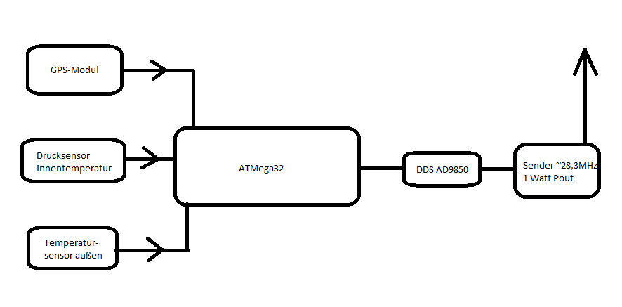
A relatively complex application such as the telemetry unit presented here requires the use of a computer system on board the balloon payload. Today, this can be done quickly and inexpensively with a so-called “microcontroller”. A chip by manufacturer ATMEL, an AVR ATMega32 type, is used. In the module presented, it is responsible for all data processing in the system.
In particular, it reads the data from the various sensors and processes it further on. It also controls the frequency generation module, which forwards the calculated data to the power transmitter, which in turn emits radio signals via an antenna so that they can be received up by the ground station. The required software was developed by the author in the “C” programming language with the freely available GNU-C compiler (AVR-GCC for Linux or Windows) for the microcontrollers of the AVR series. The corresponding code can be found in excerpts from the corresponding text passages.
The sensors in use
A flight into the stratosphere offers the opportunity to collect a wide range of data. The following environmental data is continuously recorded during the flight by the payload system developed for the balloon launch at the Alfred Grosser School Center Bad Bergzabern:
- Internal temperature in the polystyrene container of the payload,
- Outside temperature,
- Air pressure,
- GPS position,
- Battery voltage.
Block diagram of the transmission system
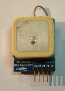
GPS board
When choosing the more complex sensors (GPS and air pressure), commercial products (“off-the-shelve”) were used. These are offered for the Arduino experimental platform, which also uses AVR controllers. They can be universally connected to any microcontroller. With the circuits installed here, data is transmitted either with an RS232 interface or an I²C bus. The sensor for the simple measurement task “outside temperature”, on the other hand, is a PTC element of type KT81-210. It is fed directly to a channel of the analog-digital converter (ADC) of the microcontroller via a voltage divider. Its parameters must be measured before installation and the voltage divider calculated accordingly. The same applies to the battery voltage detection, which was implemented using a 1: 4 voltage divider.
The GPS module
This module is being offered commercially for around 8€ with a well-known internet shopping website.
The data from the GPS module are transmitted serially via the RS232 interface. To do this, the serial interface of the ATMega32 must be configured to a transfer rate of 9600 baud. This is done by calling up the following program sequence once in the controller software:
//Init UART
void uart_init()
{
    /* 9600 Baud */
    UBRRL = 51;
    UBRRH = 0;

    /* RX and TX on INT activate */
    UCSRB = (1<<RXEN)|(1<<TXEN)|(1<<RXCIE);

    /* 8 data bits, 1 stopbit, no parity */
    UCSRC = (1<<URSEL)|(1<<UCSZ1)|(1<<UCSZ0);
}
During operation, the GPS module alternately transmits different character strings via the serial interface to the microcontroller, which subsequently must be decoded. Each character strings start with different prefixes. If a character string is transmitted that begins with “$GPGGA” for example, this information contains: Time in UTC date, position north or south latitude, position east or west longitude, height above sea level.
An example of such a character string, terminated by a checksum (CRC):
$GPGGA,114353.000,6016.3245,N,02458.3270,E,1,10,0.81,35.2,M,19.5,M,,*50
The controller software then evaluates this specific character string and encrypts it to form a new data set, which is then transmitted by radio. However, for military reasons, GPS reception is deactivated due to the system at an altitude of approx. 12000 meters (36000 feet).
Air pressure sensor
The same applies if the rate for ascent or descent (ds / dt) exceeds a certain limit. This is to ensure that no weapon systems can be developed with the freely available modules. The sensory detection of the air pressure type “BMP180” from Bosch/Germany is used as the sensor for air pressure. This is soldered to a circuit board and provided with connections in the standard grid dimension of 2.54 cm. The price is between 2 and 3 Euros.
The module also includes a temperature sensor. It is used to measure the internal temperature of the payload box. The advantage of the BMP180 is that it is calibrated by manufacturer and the calibration data is stored in a data record inside the EEPROM of the sensor. It is read out via a two-wire line (I²C bus, TWI). The software developed by the author downloads this calibration information from the sensor and then calculates the values for the current ambient pressure and temperature. The calculation procedure is somewhat complex, as the following code excerpt shows. First, the calibration coefficients are read from the sensor using the I²C bus / TWI.
/Get the calibration values from BMP180 sensor
void BMP180_get_cvalues(void)
{
    int BMP180_regaddress[11] = {0xAA, 0xAC, 0xAE, 0xB0, 0xB2, 0xB4, 0xB6, 0xB8, 0xBA, 0xBC, 0xBE};
	int BMP180_coeff[11] = {0, 0, 0, 0, 0, 0, 0, 0, 0, 0, 0};
	int t1 = 0;

	for(t1 = 0; t1 < 11; t1++)
	{
        TWIStart();
	    TWIWrite(0xEE); //Device adress and set WRITE mode
	    TWIWrite(BMP180_regaddress[t1]); //Specify register (0xF6(MSB), 0xF7 (LSB))
	    //Restart first
	    TWIStart();
	    TWIWrite(0xEF); //Send device adress and set READ mode
	    BMP180_coeff[t1] = TWIReadACK() << 8;  //MSB
	    BMP180_coeff[t1] |= TWIReadNACK();  //LSB
	    TWIStop();
    }

    ac1 = BMP180_coeff[0];
    ac2 = BMP180_coeff[1];
    ac3 = BMP180_coeff[2];
    ac4 = BMP180_coeff[3];
    ac5 = BMP180_coeff[4];
    ac6 = BMP180_coeff[5];

    b1  = BMP180_coeff[6];
    b2  = BMP180_coeff[7];

    mb  = BMP180_coeff[8];
    mc  = BMP180_coeff[9];
    md  = BMP180_coeff[10];

}

//Calculate current air pressure
long BMP180_get_pressure(void)
{

	long up;
	long x1, x2, x3;
	long b3, b6, p;
	unsigned long b4, b7;
	int oss = 0;
	//char *buf = malloc(16);

	//Start
	TWIStart();
	TWIWrite(0xEE); //Device adress and set WRITE mode
	TWIWrite(0xF4); //Register adress
	TWIWrite(0x34); //Register value = read pressure oss = 0!
	TWIStop();

	_delay_ms(100);

	TWIStart();     //Restart
	TWIWrite(0xEE); //Device adress and WRITE mode
	TWIWrite(0xF6); //Specify register (0xF6(MSB), 0xF7 (LSB))

	//Get value
	//Restart first
	TWIStart();
	TWIWrite(0xEF); //Send device adress and set READ mode

	//Copy data to buffer
	up  = (long) TWIReadACK() << 8;  //MSB
    up |= (long) TWIReadNACK();      //LSB

	TWIStop();

	//Calculate real pressure
	b6 = b5 - 4000L;
    x1 = (b2 * ((b6 * b6) >> 12)) >> 11;
    x2 = (ac2 * b6) >> 11;
    x3 = x1 + x2;
    b3 = (((ac1 * 4 + x3) << oss) + 2) >> 2;
    x1 = (ac3 * b6) >> 13;
    x2 = (b1 * ((b6 * b6) >> 12)) >> 16;
    x3 = ((x1 + x2) + 2) >> 2;
    b4 = (ac4 * ((unsigned long) x3 + 32768L)) >> 15;
    b7 = ((unsigned long)up - b3) * (50000L >> oss);
	p = (b7 < 0x80000000UL) ? ((b7 << 1) / b4) : ((b7 / b4) << 1);
    x1 = (p >> 8) * (p >> 8); //???
    x1 = (x1 * x1 * 3038L) >> 16;
    x2 = (-7357L * p) >> 16;
    p += ((x1 + x2 + 3791L) >> 4);

	return (p);

}
A presentation of the C code for the BMP180 and the STM32F4 MCU is to be found on my Github repo (click here).
After calculating the current temperature and the ambient pressure, these data are also transferred to the radio module for transmission via I²C bus.
Outside temperature measurement and battery voltage monitoring
Measuring the outside temperature is particularly interesting when flying into the stratosphere. This is solved very easily with a simple analog circuit. The microcontroller has a 10-bit analog-digital converter (ADC, analog-digital converter) that converts voltages in the range 0 <= U <= 5 V into a numerical value between 0 and 1023. This resolution is sufficient for an analog temperature measurement on the basis of a temperature-dependent resistance. Here is the extract from the complete circuit for the analog sensors:
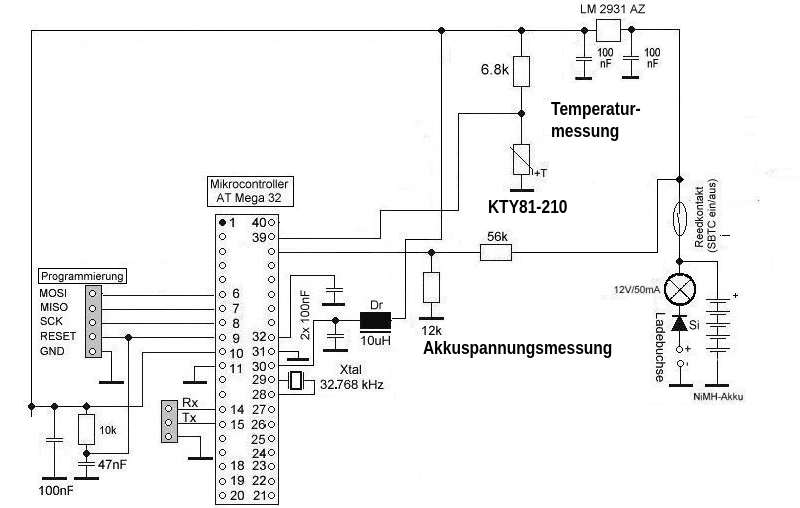
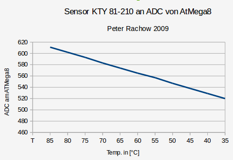
The KTY 81-210 sensor is a PTC element (positive temperature coefficient). As a PTC, aka ” thermistor”, its electrical resistance increases with temperature. A measurement made on an ATMega8 controller for evaluation purposes resulted in a linear function T => R[PTC].
DC voltage measurement
The circuit for battery voltage monitoring is achieved in a similar way. In this case a voltage divider is used to derive a maximum voltage divided below 5 V from the 12V of the payload’s electrical system. Its circuit is also entered in the circuit diagram above. 2 resistors (56kOhm and 12kOhm) divide the battery voltage down to a voltage that is below 5V even when the battery is slightly overcharged. Higher voltages on the ADC would cause problems in the microcontroller. The following applies to the battery voltage to be measured:
![]()
(ADC: numerical value determined by the analog-digital converter, UAkku = battery voltage)
Generating transmission frequency
Before the radio signal can be transmitted, it must be generated. There are various methods for doing this. In the past one would have used a crystal-controlled transmitter, for example, which would have been frequency modulated with the binary information separated by the respective “shift”. This technology is obsolete today because there are powerful and inexpensive micro-components that can generate a high-frequency sinusoidal signal directly. This process is called “direct frequency synthesis” (DDS, direct digital synthesis).
A chip made by “Analog Devices”, type AD9850, is used for the radio module described here. This is available ready-made and fitted with the necessary peripheral circuitry. In the selected configuration, however, a proprietary circuit development was preferred, which results in a purer spectrum for the output signal and which has been optimized with regard to its high-frequency properties.
The DDS module of type AD9850 contains, among a parallel one, an SPI interface (serial peripheral interface) that can be controlled by the microcontroller. The software defines instructions which frequency is to be generated in which phase position it is. In terminology of the manufacturer, this is called a “frequency word”. The frequency word is a binary sequence of numbers (32 bits wide) that is to be calculated using an algorithm specified by the manufacturer in the data sheet. Link to the manufacturer or product: http://www.analog.com/en/products/rf-microwave/direct-digital-synthesis/ad9850.html
Depending on an external quartz-controlled clock generator the DDS chip puts out a precisely defined frequency. The AD9850 can generate frequencies of up to approx. 40 MHz with an accuracy of less than 0.1 Hz. The clock generator must then work with approx. 125 MHz. The two frequencies “Mark” and “Space” for the transmission signal are now generated directly at the level of the output frequency (approx. 28.320 MHz). Mixing or converting an audio sound signal (modulation) in a complex transmitter is therefore not necessary. This direct method is called “FSK” (frequency shift keying) in contrast to AFSK (audio frequency shift keying) which modulates an audio tone to a radio transmitter. It considerably simplifies the processing of the transmission frequency.
The data structure of the communication between the microcontroller and the DDS chip
Only 3 control lines are required for data transmission between the MCU and the DDS chip:
- W_CLK (the clock signal that synchronizes both modules),
- FQ_UD (a line that goes to logic 0 as long as data is being transmitted and its change to “hi” indicates the end of the data stream) and
- DATA (the actual data for frequency synthesis) Principle of data transmission:
![]()
The associated timing diagram has the following sequence:
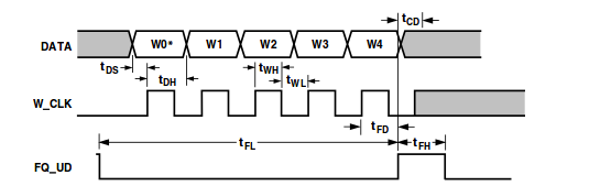
Source AD9850 datasheet
These three control lines are assigned to different ports of the microcontroller. This results in the following two functions in the software used which control the DDS chip.
//************/
//    DDS
//
//************/
//Send one bit to DDS
void spi_send_bit(int sbit)
{

    //set or clear data bit
	if(sbit)
	{
		PORTD |= 32;  //SDATA Bit PD5 set
	}
	else
	{
		PORTD &= ~(32);  //SDATA Bit PD5 clear
	}

	//W_CLK hi
	PORTD |= 64;  //Bit PD6 set

    //W_CLK lo
	PORTD &= ~(64);  //Bit PD6 clear

}

//Set AD9850 to desired frequency
void set_frequency(unsigned long fx)
{
    unsigned long clk = 125000000;
    unsigned long x;
	unsigned long hibyte, lobyte;
	int t1;

    double fword0;
    unsigned long fword1;


	//Split multiplication by 2^32 into 2 parts to avoid wrong
	//calculation (reason: 2^32 = 0 in 32 bit number!)
    fword0 = (double) fx / clk * 65536;
    fword1 = (unsigned long) (fword0 * 65536);
	hibyte = fword1 >> 16;
    lobyte = fword1 - (hibyte << 16);

    //Send 32 frequency bits + 8 additional bits to DDS
	//Start sequence
	PORTD &= ~(16); //FQ_UD lo => Bit PD4 = 0

	//W0...W15
	x = 1;
	for(t1 = 0; t1 < 16; t1++)
    {
       spi_send_bit(lobyte & x);
       x *= 2;
    }

	//W16...W31
	x = 1;
	for(t1 = 0; t1 < 16; t1++)
    {
       spi_send_bit(hibyte & x);
       x *= 2;
    }

	//W32...W39
	for(t1 = 0; t1 < 8; t1++)
	{
	    spi_send_bit(0);
	}

	//Stop  sequence
    PORTD |= 16; //FQ_UD hi => Bit PD4 = 1

}
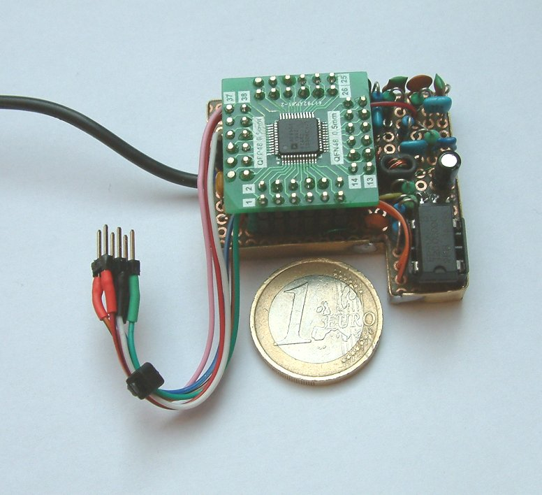
The function named set_frequency() receives the designated frequency as single parameter. The hardware of an improved DDS oscillator projected by the author (with an AD9951 instead of an AD9850) can be seen on the following circuit diagram:
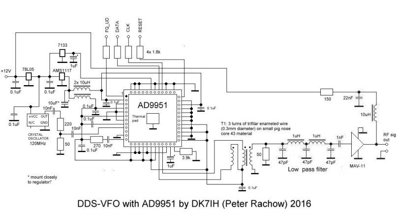
Example board:
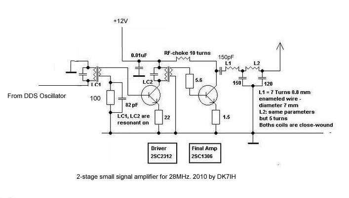
The power transmitter
The digitally generated analog transmission signal must now be amplified to an output power of approx. 250mW to 500mW, filtered and sent to the antenna. The designed power transmitter consists of only 2 amplifier stages, a driver and an output amplifier stage. Both are equipped with bipolar transistors of type 2SC1957. When selecting the transistors, make sure that their transit frequency (fT) is 8 to 10 times higher than the transmission signal to be generated. Otherwise the amplification factor of the two amplifier stages would be too low. The circuit of the transmitter (equipped with other transistors of similar fT):
The transmit antenna
A wire antenna connecting the balloon and the payload was used as antenna. It is a so-called “J antenna”. An easy to build and simple construction.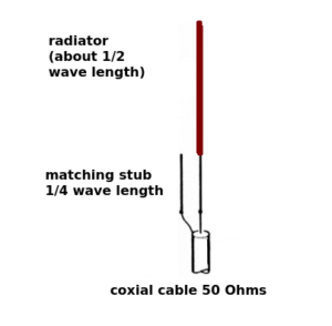
As can be seen in the picture, the J-antenna has a radiator length of half a wavelength, connected to a matching stub of ¼ wavelength. This results in a total length of approx. 7.5 meters for the frequency range used here. The purpose of the matching line is to transform the impedance from the high-Z feeding point of the half-wave radiator (Z ~ 2000 ohms) to the low-Z impedance of the antenna base point of approx. 50 ohms, so that the antenna can be connected to the transmitter output without any loss of power due to mismatching. Strictly speaking, the matching line is a quarter-wavelength “Lecher” line.
Results
In practical flight situation the signals could be received up to a flight altitude of about 40.000 ft. The signal then faded very quickly. This can be explained by the long flight distance from the “lift-off”-point as well as with ionospheric phenomenons. The balloon was, about 2 months post flight, recovered near the city of Heilbronn/Germany very close to the Neckar river about 70 km away from “lift off” point. It had landed in a field where a farmer picked it up just before overriding it with a harverster machine. Data and camera could be recovered. The whole flight, that lasted about 3 hours, has been recorded on a GoPro camera.
The video shows the flight phase where maximum altitude was reached shortly before the balloon burst and the unit starts descent back to earth:
https://www.youtube.com/watch?v=xb1fRrgPsz0