
0 Abstract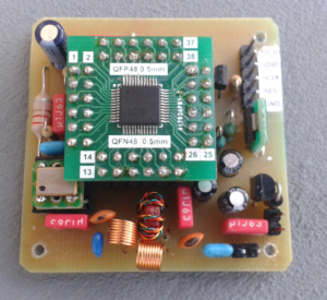
A very compact software code to control a Direct Digital Synthesizer (DDS) will be presented that will enable an STM32F4 to directly generate sine waves by using an advanced DDS system (AD9951 by Analog Devices).
1 DDS basics
DDS is a technology to directly synthesize high frequencies in the radio spectrum by specialized hardware. DDS is common in radio equipment because it provides an accurate and frequency stable method of generating radio signals without any tuned oscillators. Hence frequency stability is outstanding compared to tuned free running oscillators , frequency drift only occurs when the crystal oscillator, that is mandatory for using a DDS chip, is not stable in itself.
2 Principles of DDS operation
A direct digital synthesizer consists of multiple parts joined in a common system:

(Source: https://www.digikey.de/de/articles/techzone/2019/mar/the-basics-of-direct-digital-synthesizers-ddss)
The 2 units on the left side provide the mathematical calculation of the output frequency. This frequency usually is defined in a so called “frequency word”, which is represented by a 28 to 32 bit integer. This allows frequency resolution down to a fraction of 1 Hertz. The decisive part is a “Phase Accumulator”. In this unit a variable is counted up and re-started with its initial value of 0, when a given upper margin has been reached. The increase rate of this up-counting process depends on the frequency word:
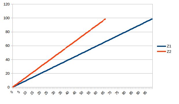
In the diagram 2 different frequencies are represented. A relatively low one (Z1) with a moderate slope rate. Another one (Z2) is higher than Z1 which is recognizable by its steeper increase function. With infinite perpetuation of this counting we get a sawtooth wave:
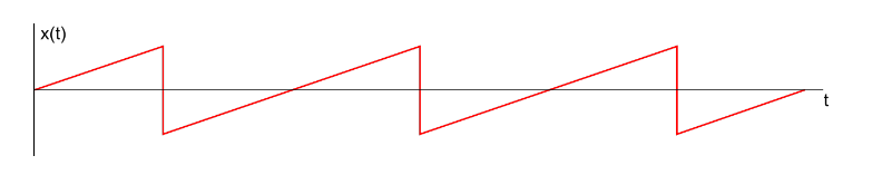
Next step is to transfer this sawtooth wave into a sine wave. The method applied here is also a one based on mathematics. Inside the DDS chip a sine wave lookup table is included. This defines a given value based on a sinusoidal function for each part of the sawtooth from 1st to last position. This transfers the phase of the sawtooth function into a sine wave. Result is that the sine wave’s frequency depends on the slope rate of the sawtooth function.
Last part of the circuit chain is a low pass filter that eliminates spurious and other unwanted signals form the output waveform thus delivering a relatively pure sine wave.
The DDS module we are talking about in this article (AD9951) is able to be clocked up to a frequency of 400MHz which theoretically provides a maximum output frequency of one third of this, resulting in 133 MHz.
3 Software considerations
The DDS made by Analog Devices (AD) communicates with the microcontroller (MCU) via an SPI bus. In this code example we will use a “homemade” SPI function instead of talking advantage of the “built in” SPI functionality provided by the STM32F4 MCU.
First it is custom to define the output lines for the DDS:
// PIN and PORT definitions for AD9850 lines connected to PORT A
#define DDS_GPIO GPIOA
#define DDS_SDIO 0  //white
#define DDS_SCLK 1  //blue
#define DDS_IO_UD 2 //yellow
#define DDS_RESET 3 //gray
(Hint: The colors behind each definition just represent my common line colors in my hardware)
In main() function we define these ports as output:
//DDS
//Put pin A0..A3 in general purpose output mode
DDS_GPIO->MODER |= (1 << (DDS_SCLK << 1));
DDS_GPIO->MODER |= (1 << (DDS_IO_UD << 1));
DDS_GPIO->MODER |= (1 << (DDS_SDIO << 1));
DDS_GPIO->MODER |= (1 << (DDS_RESET << 1));
After a short delay DDS chip is put into reset mode and afterwards released:
//Reset AD9951
delay(100);
//Reset DDS (AD9951)
DDS_GPIO->ODR |= (1 << DDS_RESET);
delay(100);
DDS_GPIO->ODR &= ~(1 << DDS_RESET);
delay(100);
DDS_GPIO->ODR |= (1 << DDS_RESET);
Next we are ready to define a frequency and let the DDS produce the signal. Two functions are needed for this purpose. The first is the hardware interface sending the frequency word to the DDS, the second defines this frequency word.
/////////
// SPI //
/////////
void spi_send_byte(unsigned int sbyte)
{
int t1, x = (1 << 7);

    for(t1 = 0; t1 < 8; t1++)
    {
        DDS_GPIO->ODR &= ~(1 << DDS_SCLK); //DDS_SCLK lo

        //Bit set or erase
        if(sbyte & x)
        {
            DDS_GPIO->ODR |= (1 << DDS_SDIO);
        }
        else
        {
            DDS_GPIO->ODR &= ~(1 << DDS_SDIO);
        }

        DDS_GPIO->ODR |= (1 << DDS_SCLK); //DDS_SCLK hi
        x >>= 1;
    }
}

//Set frequency for AD9951 DDS
void set_frequency(unsigned long frequency)
{
    unsigned long f;
    unsigned long fword;
    int t1, shiftbyte = 24, resultbyte;
    unsigned long comparebyte = 0xFF000000;

    f = frequency; //Offset because of inaccuracy of crystal oscillator

    //Calculate frequency word from f
    //frequency_word f * 2³² / fClk

    //Clock rate = 400MHz
    fword = (unsigned long) f * 10.73741824;

    //Start transfer to DDS
    DDS_GPIO->ODR &= ~(1 << DDS_IO_UD); //DDS_IO_UD lo

    //Send instruction bit to set fequency by frequency tuning word
    spi_send_byte(0x04);

    //Calculate and transfer the 4 bytes of the tuning word to DDS
    //Start with msb
    for(t1 = 0; t1 < 4; t1++)
    {
        resultbyte = (fword & comparebyte) >> shiftbyte;
        comparebyte >>= 8;
        shiftbyte -= 8;
        spi_send_byte(resultbyte);
    }

    //End transfer sequence
    DDS_GPIO->ODR |= (1 << DDS_IO_UD); //DDS_IO_UD hi
}
The formula for the frequency word (frequency_word f * 2³² / fClk) is defined in the AD9951 datasheet (p. 12). To save computing power and avoiding recalculation of a float number the fixed factor 2³²/fClk is calculated once and then reused. For other system clock rates we get:
//Clock rate = 100MHz
//fword = (unsigned long) f * 42.94967296;

//Clock rate = 110MHz
//fword = (unsigned long) f * 39.045157236;

//Clock rate = 125MHz
//fword = (unsigned long) f * 34.358675;

//Clock rate = 200MHz
//fword = (unsigned long) f * 21.47478;

//Clock rate = 400MHz
//fword = (unsigned long) f * 10.73741824;
The full software code can be found on my Github repo.