
Abstract
This article shows how to apply an off-the-shelf time signal receiver to an STM32F4, refers about the signal coding and describes the necessary software written in “Embedded C”.
Hardware
Receiver modules are available through various vendors on the internet, a respective search pattern could be this one.
Time signal transmitters
In the LF bands there are a handful (at least) of stations available that provide a standardized time signal based on the time markers produced by high accuracy atomic clocks. In central Europe DCF77 is the a well known time signal station for radio controlled clocks and watches.
The call sign “DCF77” originates from “D” which is for “Deutschland” (Germany), “C” stands for LF and “F” is for the proximity for Frankfurt/Main. DCF77’s output power is about 50kW of which about 30kW are transmitted into the atmosphere. You can see the station’s facilities on Google Maps.
Other transmitters are sited in the UK, USA, Japan etc:
- DCF77 (Germany) in Mainflingen in Hessen
- MSF (UK) in Anthorn
- JJY (Japan)
- WWV (USA) in Fort Collins, Colorado
- WWVH (USA) in Hawaii
- BPC (China) in Shangqiu (Source)
DCF77 is intended for reception within a range of max. 2000km, thus it covers most of the central of Europe. Ground wave propagation is possible within a radius of about 600km from Frankfurt, sky wave might reach up to between 2000 to 2500km. But even greater distances occasionally have been reported.
Other stations transmit on lower frequencies, MSF for example (from Northern England) on 60 kHz. Some of the off-the-shelf available receiver modules are capable of alternating the reception frequency by soldering the on-board clock crystal (32768 kHz) to another terminal on the PCB.
Signal structure of DCF77
DCF77 uses amplitude modulation (AM). The signals amplitude is reduced down to about 15% of its nominal power thus defining 2 different states:
- Full amplitude
- Reduced amplitude
Therefore binary information can be coded. Usually with the off-the-shelf receivers available on the market you will find a “low” signal when the transmitters amplitude is “high” and vice versa. Every second one pulse is transmitted. There is one exception: The last second of every minute this pulse is cancelled marking the beginning of the next minute. A pulse’s length defines the “1” or “0” state of the respective bit. This makes the signal that you can see with the receivers output pin:
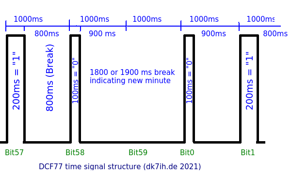 DCF77 signal structure as put out by the receiver
This receiver output makes decoding easy because this output signal can be fed directly to a digital pin of the microcontroller.
As mentioned before, the gap (missing bit 59) between bit 58 and bit 0 is the marker for a new minute to start. If pause length is longer than, let’s say 1200ms, you can deduce the next minute is starting right now. The transmitter always transmits the following minute, so if you have read 58 bits completely, this represents the data of the current minute.
The single bits have got the following representations:
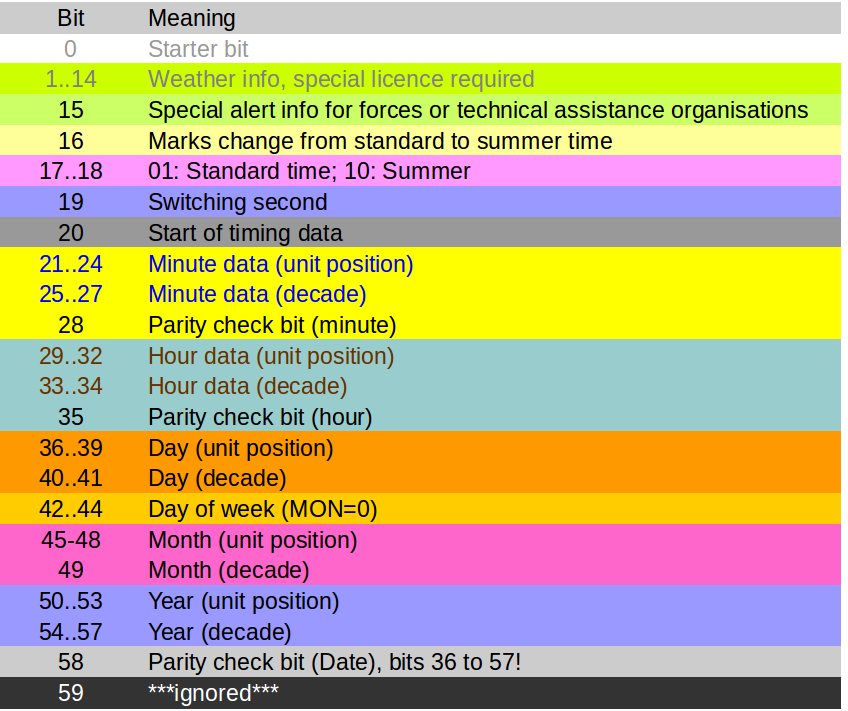 DCF77 bit coding
There are two “weird” things to be mentioned:
- Where a two-digit number has to be transmitted, the decade comes first, then the unity position follows, each of them binary coded. Both digits thus are transmitted individually!
- Byte order is LSB first!
The Software
The code is written in “Embedded C” (GNU CC) and can be downloaded from my Github repo.
Algorithms
Timing and measuring pulse length
For this software, where time lapse decoding is applied, precise timing is mandatory. This software uses an STM32F411 MCU clocked with an external oscillator (crystal) f=25MHz and setting internal clock rate by applying integrated PLLs to 100MHz. There is an interrupt routine that increases a counter every millisecond so the the duration of a pulse can be measured precisely in 1/1000 of a second.
Timer setup for the STM32F4 (f.clock=100MHz) for a 1ms counter rate:
////////////////////////////////
// TIMER2 Millisecond counter //
////////////////////////////////
RCC->APB1ENR |= (1 << 0); //Enable TIM2 clock (bit0)

//Timer calculation
//Timer update frequency = TIM_CLK/(TIM_PSC+1)/(TIM_ARR + 1)
TIM2->PSC = 100000; //Divide system clock (f=100MHz) by 100000 -> update frequency = 1000/s
TIM2->ARR = 1; //Define overrun after 1ms

//Update Interrupt Enable
TIM2->DIER |= (1 << 0);

NVIC_SetPriority(TIM2_IRQn, 2); //Priority level 2
NVIC_EnableIRQ(TIM2_IRQn); //Enable TIM2 IRQ from NVIC

TIM2->CR1 |= (1 << 0); //Enable Timer 2 module (CEN, bit0)
First a prescaler (TIM2->PSC) is set that divides clock by 100,000. Timer 2 is therefore set to an “update frequency” of 1000Hz, thus the counter is increased 10000 times per second. TIM2->ARR defines when the register is overrun. Overrun takes place now every 1/1000 seconds.
If the value of 1 has been reached, an interrupt is triggered and the respective interrupt service routine is called once. This routine increases a milliseconds counter by one:
  /////////////////////////////
 // TIM2 INT Handler //
/////////////////////////////
extern "C" void TIM2_IRQHandler(void)//IRQ-Handler for TIM2
{
    if (TIM2->SR & TIM_SR_UIF) //Toggle LED on update event every 500ms
    {
        ms0++;
    }
    TIM2->SR = 0x0; //Reset status register
}
With this setting it is possible to decode the timing of the incoming signals very exactly. This is done inside a loop structure, first the loop waits for a pause of a length to be measured. Afterwards, when a bit present, the software takes the “hi”- time of the pulse an decides if this represents a “1” or a “0”. Refer to the main()-function in the code.
First all the 58 bits are recorded and stored into an integer array of appropriate length, later the parity checks are performed to estimate the likelihood of a valid signal. With this very simple kind of check it it absolutely possible that there is a faulty result that could not be detected.
Parity checking
A simple way of checking plausibility of data is included by doing a parity check:
int get_parity(int b[], int sta, int end)
{
    int t0, n = 0;

    for(t0 = sta; t0 < end + 1; t0++)
    {
        if(b[t0])
        {
            n++;
        }
    }

    if((n / 2) * 2 == n)
    {
        return 0; //even parity
    }
    else
    {
        return 1; //odd parity
    }
}
The number of “1”s in a specific part of the data stream, defined by “start” and “end” are counted. If the number is even, the function returns “0” which stands for “Even parity” and vice versa.
If you need higher security for error-free receive operation, plausibility checks should also be included. In my software, because I live about 150km from Frankfurt and therefore have sufficient field strength all over the day and night, I did not apply functions for enhanced error checking.
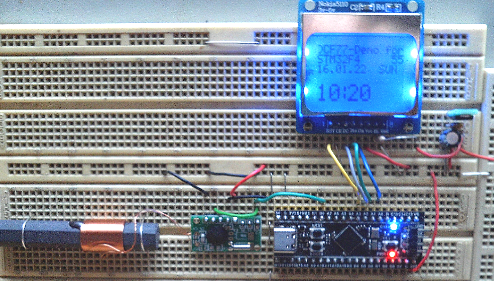
The receiver’s signal subsequently is fed into PB0 port, a LED connected to PC13 onboard the “Blue Pill”-board provides an optical indicator if the signal level is OK. You should see a 1 second clock rate here with pulses of two different lengths.
The software takes advantage an OLED display with TWI connection (SDA, SCL) and uses SH1106-chipset/driver to display all the data on screen. On the picture you can see the version for the Nokia51150 SPI LCD.
Software
You can download full code here: https://github.com/DK7IH/STM32-F4-Demos/tree/main/_DCF77
Thanks for watching!
Peter (DK7IH)