
Abstract
The basics of driving this standard display will be explained and the crucial code sequences will be presented. A universal code for driving the LCD in 4-bit mode will be discussed.
The Basics on LCD 162
Picture source: https://www.researchgate.net
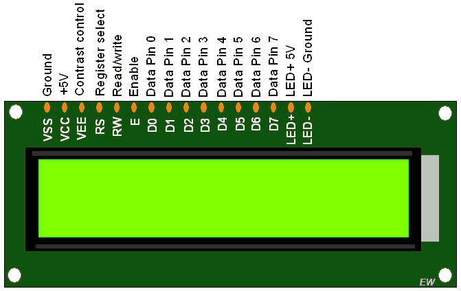
One of the most widely used display types are the so called DOT-Matrix displays. They com in different sizes for different number of lines and characters per line. The most widely known is the “2 lines, 16 characters” display.
They usually have a 16 pin header. There are 3 control and 8 data lines.
Controls:
- RS: Active low, activates the display
- RW: Sets write (lo) or read (hi) operation
- E: Enable: Sets LCD ready to accept data from MCU
Data lines: The display can be driven in 8- or 4-bit mode. For the 1st mode all 8 data bits are transmitted simultaneously (bit 7..0), in 4-bit data is split into a high nibble (4 MSBits) and a low nibble (4 LSBs). Which mode is used is subject to the initialization procedure. Normally, to save lines with the MCU, the 4-bit mode is preferred.
These LCDs are suitable for 5V devices and also work fine with the 3.3V STM32F MCUs in the most cases.
LED backlight (if present) must be connected via a resistor depending on the display type backlight. For the “old” green LCDs with LED backlight this resistor should be >39Ω when powered by 5 V and >220Ω when powered by 12V. For the blue LCDs available it can be 150Ω when backlight is connected to a 5V line.
Remember: It is always important to look into the data sheet.
Driving the LCD
First it is recommended to define the control and data lines within your code:
#define LCD_GPIO GPIOA
#define LCD_RS 5 //PA4 green
#define LCD_RW 6 //PA5 blue
#define LCD_E 7 //PA6 yellow
#define LCD_D0 8 //PA8 violet
#define LCD_D1 9 //PA9 lightgreen
#define LCD_D2 10 //PA10 gray
#define LCD_D3 11 //PA11 orange
#define DATAPIN0 8 //Set to number of first data pin on MCU, e. g. set
                   //to 8 if data port starts with A8 the value would be 8
As lots of possibilities might exist the code is kept in a universal manner. Usually we will connect the whole LCD to one single GPIO port. Data pins will be kept together, for example from PA3…PA0.
Writing data to the LCD
A procedure to write data to the LCD looks like this:
void lcd_write(char lcdmode, unsigned char value)
{
    uint8_t nh = (value >> 4) & 0x0F;
    uint8_t nl = value & 0x0F;

    while(lcd_check_busy()); //Check busy flag

    LCD_GPIO->ODR &= ~(1 << LCD_RW); //Set RW to write operation, i. e. =0

    if(!lcdmode)
    {
        LCD_GPIO->ODR &= ~(1 << LCD_RS); //CMD
    }
    else
    {
        LCD_GPIO->ODR |= (1 << LCD_RS); //DATA
    }

    LCD_GPIO->ODR &= ~(0x0F << DATAPIN0); //Reset data port

    //HI NIBBLE
    LCD_GPIO->ODR |= (1 << LCD_E);
    LCD_GPIO->ODR |= (nh << DATAPIN0);
    delay_ms(2);
    LCD_GPIO->ODR &= ~(1 << LCD_E);

    LCD_GPIO->ODR &= ~(0x0F << DATAPIN0); //Reset data port

    //LO NIBBLE
    LCD_GPIO->ODR |= (1 << LCD_E);
    LCD_GPIO->ODR |= (nl << DATAPIN0);
    delay_ms(2);
    LCD_GPIO->ODR &= ~(1 << LCD_E);
}
First data is split up into the two 4-bit nibbles. Next is defined that data is to be written (data can also be read from RAM) and if data or command is transferred in the current transmission. Then the data lines are reset and the two nibbles re transferred sequentially. A wait state ensure proper transmission and might be shortened depending on the respective display.
Initialization
The first sequence of code in your main() program will perform the init procedure. These settings are also described in the data sheet.
//Init LCD
void lcd_init(void)
{
    // Basic settings of LCD
    // 4-Bit mode, 2 lines, 5x7 matrix
    lcd_write(0, 0x28);
    delay_ms(2);
    lcd_write(0, 0x28);
    delay_ms(2);

    // Display on, Cursor off, Blink off
    lcd_write(0, 0x0C);
    delay_ms(2);

    // No display shift, no cursor move
    lcd_write(0, 0x04);
    delay_ms(2);
}
Writing a character the LCD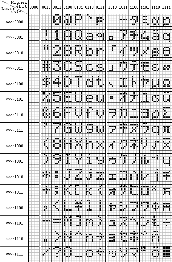
To write a given character you must identify its respective code from data sheet. On the left the codes are represented. For letters and numbers they go along with the commonly known ASCII codes. The letter “A” for example is identified by code number 65.
A simple function writes a given character into the RAM of the LCD:
//Send one char to LCD
void lcd_putchar(int row, int col, unsigned char ch)
{
    lcd_write(0, col + 128 + row * 0x40);
    lcd_write(1, ch);
}
The definition of this procedure is explained in data sheet. A row and column must be defined as can be seen in the code. This procedure may vary when using different LCD DOT-Matrix display type depending on the number of lines.
The rest to be done are the so-called “goodies” that are setting up on these basic functions, like displaying strings and numbers etc. A full code example can be downloaded from my Github Repo.