
Abstract
A very widely used type of OLED is the SS1306/SS1106 chipset family. A driver for the STM32F4/ARM-Cortex M4 microcontroller will be described. Some of the these OLEDs are available with either SPI or I2C interface. We will refer only to the I2C type in this article.
Available types of the SS1306/1106 chipset OLEDs
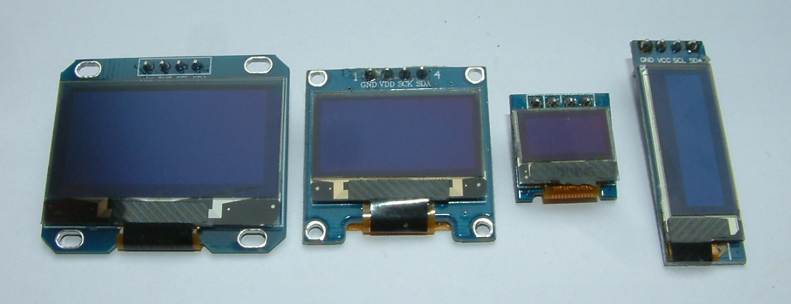
OLED types (from the left): SH1106 128×64 (1.3″), SH 1306 128×64 (0.96″), SH 1306 64×32 (0.49″), SSD1306 128×32 (0,93″)
As you might have realized, there are 3 different types of chipsets used:
- SH1106
- SH1306
- SSD1306
The first 2 are very much software compatible. Only one parameter hast to be changed to make software portable from SS1106 to SS1306 for example. SSD1306 instead uses a different type of addressing which means that a separate driver has to be written.
Software driver for SS1106/SS1306 OLED
As the interfacing is via I2C and in case you are not familiar with tha it is recommend to read the referring section in my online tutiral an register oriented programming the STM32F4 MCU (Link). The ful code for the driver can be found on my Github repo (SS1106 or SS1306), both for 128×64 pixel resulution.
Explaining the code
The I2C stuff in this project is not primarily relevant to our goals. Except from the fact htat one should have the I2C address of these OLEDs in mind:
device_addr = 0x78; //I2C address of device
They have been defined by the manufacturer of the breakout boards the OLEDs are soldered to.
Initializing the OLED
Init procedure is relatively complex. All settings must be software defined in an init sequence. One example looks like this:
//Initialize OLED
void oled_init(void)
{
    oled_command(0xAE); // Display OFF
    oled_command(0x20); // Set Memory Addressing Mode
    oled_command(0x00); // HOR

    oled_command(0xB0); //Set Page Start Address for Page Addressing Mode, 0-7
    oled_command(0xC8); //Set COM Output Scan Direction
    oled_command(0x00); //--set low column address
    oled_command(0x10); //--set high column address
    oled_command(0x40); //--set start line address
    oled_command(0x81);
    oled_command(0xFF); //Set contrast control register
    oled_command(0xA1); //Set Segment Re-map. A0=address mapped; A1=address 127 mapped.
    oled_command(0xA6); //Set display mode. A6=Normal; A7=Inverse
    oled_command(0xA8);
    oled_command(0x3F); //Set multiplex ratio(1 to 64)
    oled_command(0xA4); //Output RAM to Display
    oled_command(0xD3);
    oled_command(0x00); //Set display offset. 00 = no offset
    oled_command(0xD5); //--set display clock divide ratio/oscillator frequency
    oled_command(0xF0); //--set divide ratio
    oled_command(0xD9);
    oled_command(0x22); //Set pre-charge period
    oled_command(0xDA);
    oled_command(0x12); //Set com pins hardware configuration
    oled_command(0xDB); //--set vcomh
    oled_command(0x20); //0x20,0.77xVcc
    oled_command(0x8D);
    oled_command(0x14); //Set DC-DC enabl
    oled_command(0xAF); //Display ON
}
These settings are usable for most applications. With some OLED contrast must be adapted, but the remaining settings can be left more or less like they are presented here.
Setting and resetting a pixel
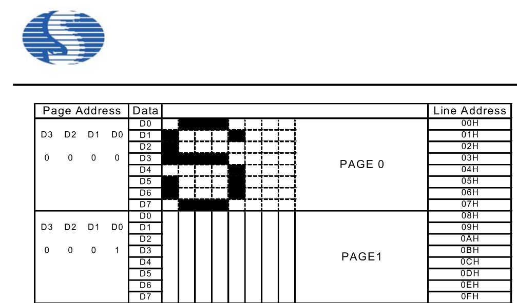
SS1106 OLED RAM organization (Source SS1106 datasheet)
To set a pixel the respective section of the OLED RAM must be addressed. The OLEDs RAM is organized in “pages” (which are more or less “lines” when you use the display as a text display. Each line is 8 pixels high which makes it suitable for text displays. Each pages contains 8 bytes of data:
To address a pixel (or a line pixel to say exactly) it is mandatory to address a page:
//Set "cursor" to current position to screen
void oled_gotoxy(uint8_t x, uint8_t y)
{
    int x2 = x; //SS1306
    //int x2 = x + 2; //SS1106


    uint8_t d[4];
    d[0] = OLEDCMD;
    d[1] = S_PAGEADDR + y;
    d[2] = S_SETLOWCOLUMN + (x2 & 0x0F);
    d[3] = S_SETHIGHCOLUMN + ((x2 >> 4) & 0x0F);
    i2c_write_bytes(d, 4);
}
With a basic parameter S_PAGEADDR defined in the header of the code plus an additional offset (y) the page is addressed. The column then is defined by 2 values according to datasheet (p. 19):
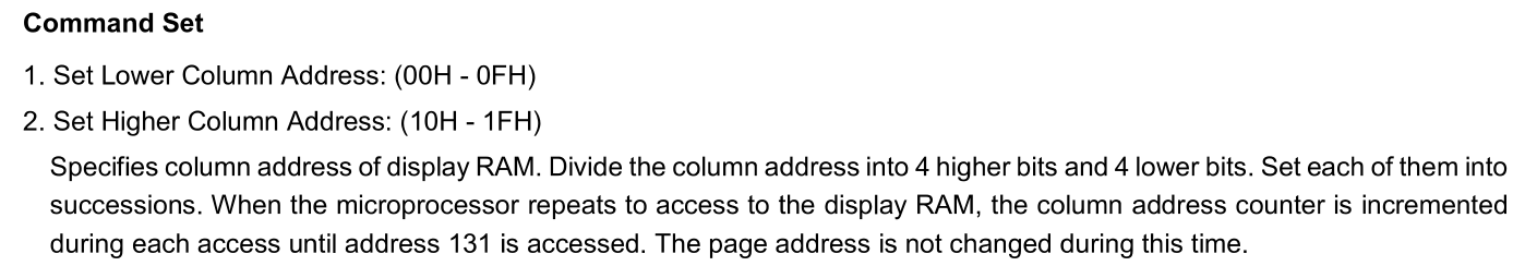
Important: Please note the intro declaration and definition of the “x2” varaiable. This defines the specific sub type of the OLED (SS1106 / SS1306)!
After having selected the destination in RAM for data, this data can be written to the OLED:
//Write character to screen (normal size);
void oled_putchar1(unsigned int x, unsigned int y, uint8_t ch, int invert)
{
    int t0;
    int n = FONTW; //Fontwidth
    uint8_t *d = (uint8_t*) malloc(n);
    int cnt = 0;

    d[cnt++] = OLEDDATA;
    oled_gotoxy(x, y);

    for(t0 = 0; t0 < FONTW; t0++)
    {
        if(!invert)
        {
            d[cnt++] = font[ch - 32][t0];
        }
        else
        {
             d[cnt++] = ~font[ch - 32][t0];
        }
    }
    i2c_write_bytes(d, cnt);
    free(d);
}
First, as mentioned before, the destination in RAM has been specified, next an array of 8×8 pixels is transferred as data stream to the OLED’s RAM. This will, in the example, display a character from the character set defined in the software. After having succeeded so far, putting out strings and numbers in the display is more or less every day software development and should not be further discussed at this point.
A general approach in writing display drivers should not be forgotten: The steps to be taken are from the simple to the more complex things: First learn to display a pixel, next a character and the letters and in the end full strings and numbers.