

Simple membrane keypads are available for some Euros/Dollars from vendors all over the world. They are numeric (digits 0..9), in addition have 4 letters (A..D) and the * and the # symbol. Basically they for are setup as a matrix, each symbol representing a standard push button. The wiring is as follows:
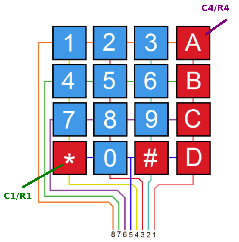 It’s easy to see: The matrix is made up from 4 columns (C1..C4) and 4 rows (R1..R4). Each time a key is pressed one specific row (pins 5..8) is connect to one specific column.
As there is no ground (GND) connector, another approach has to be found for decoding the pressed pushed button.
Decoding the keypad by software
We are using GPIOA (Pins P0..P7) in our STM32F4 MCU to work as the connector for the keypad. The first 4 pins are outputs, the latter 4 pins are inputs:
//Lines as general purpose output
for(t1 = 0; t1 < 4; t1++) //4 output lines A0..A3
{
    GPIOA->MODER |= (1 << (t1 << 1));
}

//Lines as inputs
for(t1 = 4; t1 < 8; t1++) //4 input lines A4..A7
{
    GPIOA->MODER &= ~(1 << (t1 << 1));
    GPIOA->PUPDR &= ~(1 << (t1 << 1));
}
(Source: Datasheet)
In the infinite loop of our main() software the 4 output lines representing the columns are switched through the bit patterns 0b0001, 0b0010, 0b010 and 0b1000. After the bit pattern was set, the 4 input pins (A4..A7) are checked which one of them is high. So we can identify the row and the column that has bee selected by the user.
while(1)
{
    for(t1 = 0; t1 < 4; t1++)
    {
        GPIOA->ODR &= ~(0b1111); //Bits 4:0 as 0
        GPIOA->ODR |= (1 << t1); //Set 1 coloumn bit
        for(t2 = 4; t2 < 8; t2++) //Read row pins
        {
            if(GPIOA->IDR & (1 << t2))
            {
                GPIOC->ODR &= ~(1 << 13); //Onboard Led on
                GPIOA->ODR &= ~((t2 - 3) << 8); //Row LED
                GPIOB->ODR &= ~(((3 - t1) + 1) << 12); //Col LED
            }
            else
            {
                GPIOC->ODR |= (1 << 13); //LED off
                GPIOA->ODR |= (0b111 << 8);
                GPIOB->ODR |= (0b111 << 12);
            }
        }
    }
}
For demonstration 2 sets of 3 LEDs each have been connected to VDD via a 100Ω resistor: A8, A9, A10, B12, B13 and B14 to VDD. They work as “binary” readouts displaying selected row and column as bit pattern. The software decodes the ‘*’ symbol as row1/col1, “A” is represented by “R4/C4” as shown in the picture above. You can download the full code from Github: https://github.com/DK7IH/STM32-F4-Demos/tree/main/4x4_Keypad