
Abstract
Digital sensors with various interface types (SPI, I2C, USART etc.) are widely used in the world of embedded systems. But analog sensors also play an important role in getting measurement data from our environment. In this lecture you will learn how an PTC thermal sensor is interfaced to the STM32F4 MCU. Basic approaches will be demonstrated and mathematical procedures will be explained.
The positive temperature coefficient sensor (PTC)
A PTC is a temperature dependent sensor element. Basically there are two types of sensor elements. The PTC and its “reverse mode” counterpart, the NTC. As you might guess, that the letter “N” in NTC stands for “negative”. Thus, the two sensor types show reverse T->R functions:
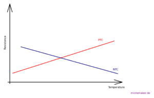
As temperature rises, an NTC decreases its resistance, the whereas the resistance in a PTC increases. From the drawn function you could assume that the curve runs linear, in practical terms it often does not. More or less. The element we are going to use is an off-the-shelf thermistor, the KTY81-210. The T->R function is defined in the device’s datasheet:
(Reference: https://www.alldatasheet.com/datasheet-pdf/pdf/17846/PHILIPS/KTY81-210.html)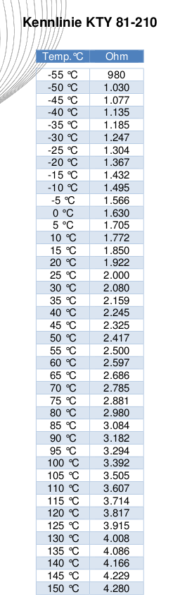
Connecting the thermistor to an MCU
The usage of the internal ADC (analog to digital converter) integrated into the ST32F4 MCU is the best choice for a low complexity setup. ADC in the STM can be configured to various bit width, in our application we will use full 12 bits capability. This means that the ADC will present numeric values between 0 <= adc_value < 4096.
Converting an ADC value to a voltage
Usually the ADC, which works on the principle of successive approximation, will convert an applied voltage to a numeric value on the basis of a linear function. Thus we get a ratio formula, in this case (12-bit ADC) with a value of 2^12 (4096) distinct steps:
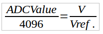
(ADCValue: numeric value as the outcome of the conversion process, Vref.: Reference voltage, usually 3.3V in an STM32F5 MCU, V: applied to the ADC’s input pin)
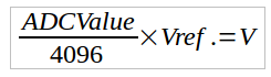
When converted to calculate the resulting voltage applied to the ADC, we get
Using a voltage divider to get the input voltage
To get a voltage that depends on the value of a (variable) resistor we usually use a voltage divider:
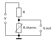
(V: reference voltage, R: fixed resistor, R.therm: thermistor, V.out: resulting voltage)
A voltage divider converts an input voltage (V) to an output voltage based also on a ratio formula. In this case it is:
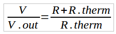
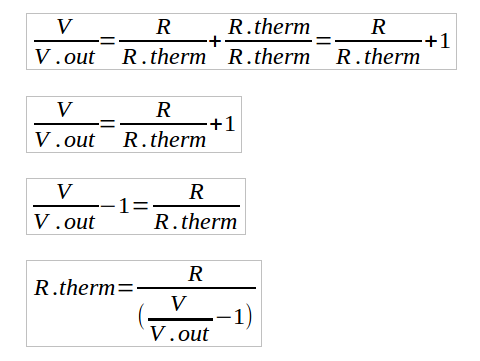
As we want to calculate R.thern we have to convert the equation, so we finally get for the thermistor’s resistance :
Calculating ambient temperature from the thermistor’s resistance
The last of the 3 steps means to convert the themistor’s resistance to a temperature value. There are several ways to achieve this. The most elegant way is to calculate temperature on the basis of a given linear function, provided the sensor element is a linear device. This must be checked by the value table in the data sheet. For the KTY81-210 we can do so in first approximation.
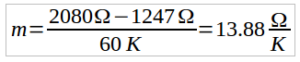
First we calculate the straight slope for the (assumed) linear function. To achieve this, we take into consideration that for a linear function straight slope is
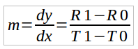
By taking two arbitrary pairs (-30°C and +30°C) out of the table above we calculate straight slope
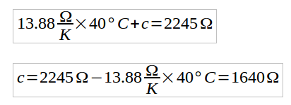
Next we have to calculate the y intercept (constant term). To get it we select another pair of data from the table (T=40°C, R=2245Ω)
With this we can setup a set of functions in our software to calculate the ambient temperature from a value supplied by the ADC. The equations appear in the same order as they have been pointed out in this tutorial.
adcret = ADC1->DR;                     //Read value in register
volt = (double) adcret * vdd / 4096;   //Convert ADCval to voltage
rtherm = r1 / (vdd / volt - 1);        //Calculate current resistance of KTY81-210 thermistor
temp = (rtherm - 1690) / 13.88 * 10.0; //Calculate temp based on function R.therm = m*T+c
                                       //derived from data sheet
To understand the usage of the ADC and the coding framework for it, is recommended checking the respective lesson in the tutorial “Register oriented programming” on this website.
A full code example (including display driver) can be found on my Github Repo: https://github.com/DK7IH/STM32-F4-Demos/tree/main/_Sensors/KTY81-210
Things to keep in mind
Voltage stability is crucial for proper function of the circuit. Thus a stabilizing capacitor (100uF, 10V) should be paralleled to the voltage divider. Also the thermal sensor element should be kept away from heat sources. Thus it is not recommended to use the internal sensor inside the STM32F4 MCU for measuring problems requiring serious approach.
If more accuracy is required, a widely used strategy is to take a sample of let’s say 10 or 20 values and calculate the average temperature and display this.