
Abstract
A simple and reliable data communication system for the ultra high frequency bands (UHF) will be presented. It applies off-the-shelf radio transmitter and receiver modules (aka “transceivers”) with a maximum output power of 10 Milliwatts (mW). It can be used for data transfer within remote control systems, point-to-point data exchange like in measurement devices etc.
The RFM12B radio transceiver module
Some radio and antennas principles
Past the recent years there have been a lot of new single-chip devices on the market that can provide an easy implementation of a complete radio system within given frequency ranges. These frequency bands are either in the so-called “ISM” bands (industrial, scientific, medical applications) or in the SHF (super high frequency) 2.4 GHz area where WiFi and Bluetooth networks are also present. In the UHF ISM-bands we have 3 distinct areas for communication. There are…
- 433 MHz
- 868 MHz
- 902MHz
The RFM12B module is available for each of the 3 bands with a separate module. The difference is in the integrated rf module and the output low-pass filter. Concerning software there are no differences. For our example we use the 433 MHz version. Higher frequencies have shorter antennas what is due to the fact that antenna length is a function of wavelength(λ) which is a reciprocal function of frequency (f). For the wavelength of a given radio frequency we calculate:
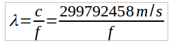
(λ: wavelength, 299,792,458m/s: velocity of light, f: frequency in Hz)
As antennas usually quarter-wavelength devices are used. These form the one half of a Hertz’ dipole. The length of such an antenna then equates to:

(l: length of radiator element, λ: wavelength)
Usually length is multiplied with a velocity factor of about 0.95 because the speed of light in vacuum differs from that on a metal conductor.
From the formula it can be deduced that antennas get shorter when frequency increases. Therefore, if antenna space is limited, the modules with higher frequencies should be used. On the other hand the propagation characteristics of radio waves change with increase in frequency. They approximate more and more to the propagation characteristics of light thus fading and other unwanted effect like signal erasement effects become stronger when these waves have to travel through or round certain types of environment like walls etc.
For the 433MHz band we calculate a wavelength of approximately 70cm which results in an antenna length of about 17 to 18 cm.
The RFM12B module (Hardware)
The RF12b module is a complete “breakout board” for the SI4421 chip by Silicon Labs. It also holds a 10Mhz clock crystal and an radio frequency output network for filtering and antenna matching. Its layout is
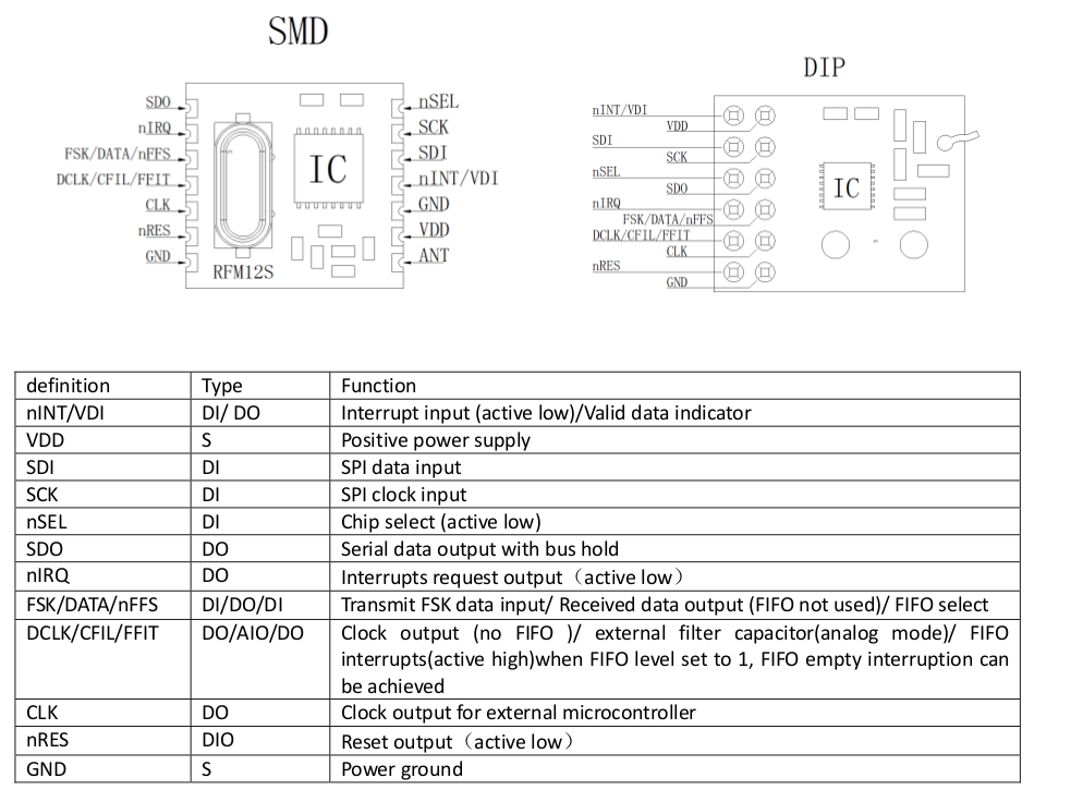
(Source: RFM12B Datasheet)
The module is designed for VDD=3.3V which makes it compatible for the STM32F4 MCUs without any level shifting required. There is also a 10 MHz clock oscillator output (CLK) that could be used for a microcontroller if there is no clock source on board.
Software Interface
Communication to RFM12B module is established via two distinct interfaces:
- The control interface (SPI)
- The data interface (FSK etc. by setting level to VDD or GND)
The control interfaces is used for setting up the module and define its parameters. The data interface is used to transmit data. Data transfer can be established in two different modes:
- “Raw” mode by using FSK (frequency shift keying)
- Using integrated protocol functions (FIFO mode)
To keep the design simple we are going to demonstrate FSK mode only within this application.
Commands
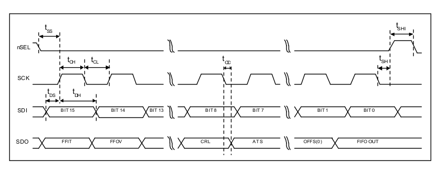
There is a set of commands described in the data sheet, starting at p. 14. The general format is as follows. Each command consists of fixed 16 bytes to be transferred via the SPI bus.
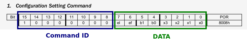
The first byte specifies the command ID, the remaining 8 bytes are the data related to the command. Bus timing is standard SPI mode. The 3 bus lines are assigned as marked in pin layout and the code for this example which will be referred by the end of the page.
(Source: datasheet)
As a developing engineer you can either decide if you prefer to use integrated SPI functions in the MCU or to create your own. Where MCUs only have 8 bit SPI capability the setup of a self created function is required. We will prefer this onset as well in the later presentation.
Hardware setup
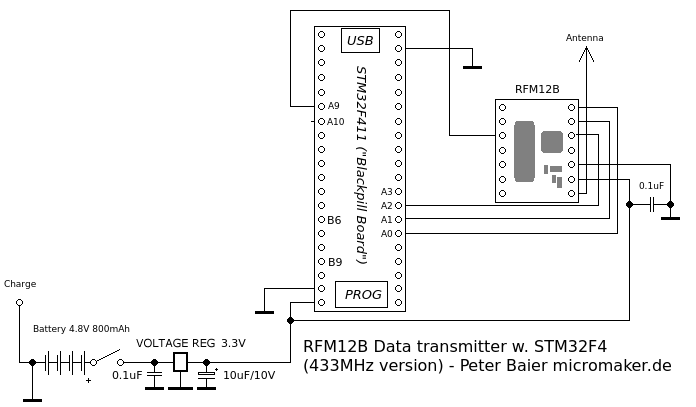
First the transmitter schematic shall be presented:
And the receiver circuit:
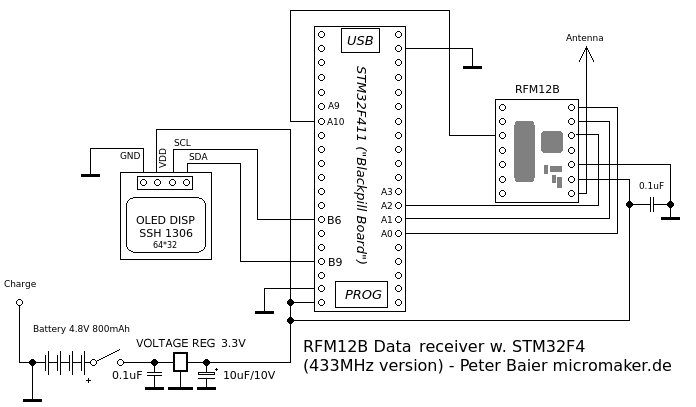
The display (an OLED) is for demonstration purposes only. The transmitter sends ASCII characters via the radio channel and the receiver decodes them. To check the incoming characters the display is used.
The Software
The code is, business as usual, written in Embedded C for the STM32F4 RISC MCUs. Please go to my Github Repo to check that out…
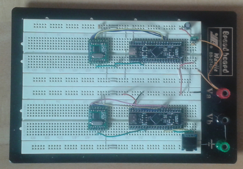
433 MHz RFM12B transmitter/receiver test setup (TX on top, RX bottom)
Achievable Range
The radio signals can be transmitted over distances of about 80 to 100 meters in open space. Correct antenna length is a must to achieve this range. Within buildings the range is much smaller, about 10 to 15 meters.