
Abstract
Interconnecting an external EEPROM of the well known 24Cxxx type to the STM32F4 MCU using the I2C bus will be demonstrated. This might be useful because STM32s don’t have internal EEPROM like AVRs and PICs do have.
Theory
24C65, 24C128, 24C256 are external EEPROM modules that can be connected to a microcontroller and expand internal EEPROM size. The ICs can be used in a wide range of DC supply values, in the range from 1.8 to 6V. Write time is fairly slow (2 ms). The connection to the MCU is done by data communication via the I²C (aka “I2C”) and the related protocol. Data rates 100kHz (VDD <= 4.5V) and 400kHz (VDD between 4.5 and 6V) are available. Endurance is high, 10000000 cycles are guaranteed for “High Endurance Block”.
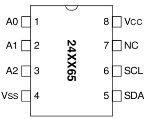
The IC comes in an 8 pin PDIP or SOIC package that are pin compatible:
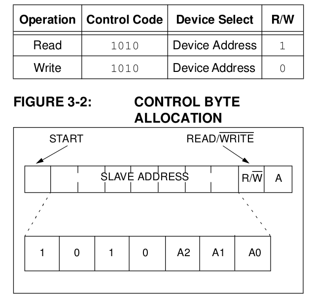
A0, A1 and A2 determine bit 3, 2 and 1 of the I2C address of the device. Bits 7..4 are always 0b1010. Bit 0 indicates read (1) or write (0) operation:
Practical setup
A simple demonstration can be found on my Github repository. It only writes a number of bytes into the EEPRM and recalls them instantly. Thus a DOT matrix display is used to verify data correctness.
Explaining the code
First I2C interface is defined:
//////////////////////////////////////////
// Setup I2C - GPIOB 6 SCK, 9 SDA
//////////////////////////////////////////
//Enable I2C clock
RCC->APB1ENR |= RCC_APB1ENR_I2C1EN;

//Setup I2C PB6 and PB9 pins
RCC->AHB1ENR |= RCC_AHB1ENR_GPIOBEN;
GPIOB->MODER &= ~(3 << (6 << 1)); //PB6 as SCK
GPIOB->MODER |= (2 << (6 << 1)); //Alternate function
GPIOB->OTYPER |= (1 << 6); //open-drain
GPIOB->MODER &= ~(3 << (9 << 1)); //PB9 as SDA
GPIOB->MODER |= (2 << (9 << 1)); //Alternate function
GPIOB->OTYPER |= (1 << 9); //open-drain

//Choose AF4 for I2C1 in Alternate Function registers
GPIOB->AFR[0] |= (4 << (6 << 2)); // for PB6 SCK
GPIOB->AFR[1] |= (4 << ((9-8) << 2)); // for PB9 SDA

//Turn on the GPIOA peripheral for LED
RCC->AHB1ENR |= RCC_AHB1ENR_GPIOCEN; //RCC->AHB1ENR |= (1<<0);
GPIOC->MODER |= (1 << (13 << 1));
GPIOC->ODR |= (1 << 13);

//Reset and clear register
I2C1->CR1 = I2C_CR1_SWRST;
I2C1->CR1 = 0;

//Set I2C clock
I2C1->CR2 |= (10 << 0); // 10Mhz periph clock
I2C1->CCR |= (50 << 0);

//Maximum rise time.
I2C1->TRISE |= (11 << 0); //Set TRISE to 11 eq. 100khz

I2C1->CR1 |= I2C_CR1_PE; //Enable i2c
// I2C init procedure accomplished. //////////////////////////
Another set of functions writes and reads the EEPROM via I2C:
void eeprom24c65_write(uint16_t mem_address, uint8_t value)
{
   uint8_t data[3];
   data[0] = mem_address >> 8; //Address of byte in 24C65 MSB
   data[1] = mem_address & 0xFF; // LSB
   data[2] = value;

   i2c_write_nbytes(data, 3);
}
An array of byte is defined. The first two bytes represent the EEPROM address, the 3rd one the value that is going to be wirtten to the respective cell in the EEPROM.
Reading data follows a similar process. A different approach has been used here. Memory address is handed over as a single variable:
uint8_t eeprom24c65_read(uint16_t mem_address)
{
    uint8_t r = i2c_read2(mem_address);
    delay_ms(5);
    return r;
}
With this simple set of functions data access to 24C65 and its derivates is possible without any fuss.