
ILI9341 parallel interface for STM32F4 (16-bit parallel display)
The ILI9341 is a universal display with a controller that has many features inherent. One is that this display can be driven using several interface modes. The mos common one is the serial (SPI) interface. A respective driver is described here.
Not that widespread is the parallel version of this LCD. Sometimes it is branded “CP11003”. It has 16 data lines but can be driven in an 8-bit parallel mode (D7:D0).
Hint: The respective display mode (8, 9, 16 or 18-bit parallel) has been hardware defined by the manufacturer of the display board. There are different models on the market that look more or less the same but must be distinguished in the bit number they use for the parallel interface. Thus different code must be written for the various displays.
The LCD uses, in addition, 4 control lines:
- RESET
- RD (active low when data is transferred from the LCD to MCU, usually not used, thus always high)
- WR (active low when data is transferred from the MCU to the LCD)
- RS (not to be mixed with “RESET”, defines if data (hi) or command (lo) is received)
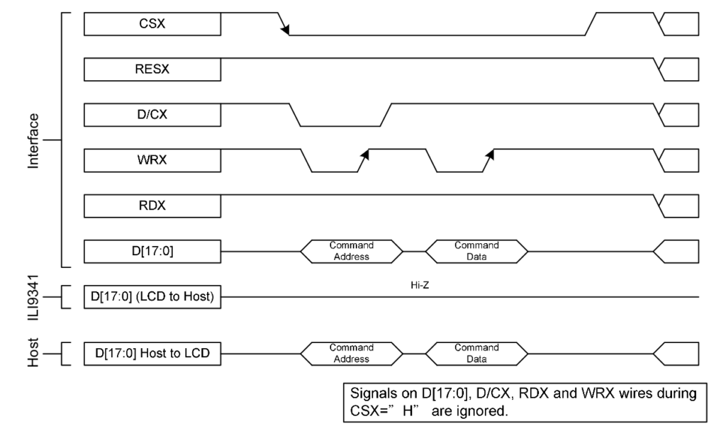
The timing diagram excerpt from datasheet (please not the RD line here is metioned as D/C (data/command)
8-bit parallel mode
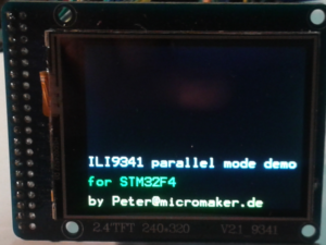
ILI9341 parallel interface for STM32F4 (8-bit parallel display)
The respective function to wirte data into the display’s RAM for this module is this one. We use GPIOA (A7:A0) as data interface and the same as control interface (A11:A8):
//Parallel output (8 bit) line defines
#define LCDGPIO GPIOA
#define LCD_RES 8 //Reset (active low)
#define LCD_RD 9 //Write operation indicator (actice low)
#define LCD_WR 10 //Read operation (actice low)
#define LCD_RS 11 //CMD (low) or DATA (high)
The function to write data to the LCD is:
//Parallel write data or command to LCD
void lcd_send(int dc, int val)
{
    LCDGPIO->ODR |= (1 << LCD_RD); //RD high to write data
    LCDGPIO->ODR |= (1 << LCD_WR);

    if(!dc) //Cmd (0) or Data(1)?
    {
        LCDGPIO->ODR &= ~(1 << LCD_RS); //Cmd=0
    }
    else
    {
        LCDGPIO->ODR |= (1 << LCD_RS); //Data=1
    }

    LCDGPIO->ODR &= ~0xFF;
    LCDGPIO->ODR |= val & 0xFF;

    LCDGPIO->ODR &= ~(1 << LCD_WR); //Transfer data
}
Drawing a pixel requires consecutive 2 write cycles
void lcd_draw_pixel(int color)
{
    lcd_send(LCD_DATA, color >> 8);
    lcd_send(LCD_DATA, color & 0xFF);
}
Before setting a pixel the location on screen must be determined. This is a two-step operation as described in data sheet of the ILI9341 (p. 83)
void lcd_set_xy(int x, int y)
{
    //X
    lcd_send(LCD_CMD, 0x2B);
    lcd_send(LCD_DATA, x >> 8);
    lcd_send(LCD_DATA, x & 0xFF);
    lcd_send(LCD_CMD, 0x2c);

    //Y
    lcd_send(LCD_CMD, 0x2A);
    lcd_send(LCD_DATA, y >> 8);
    lcd_send(LCD_DATA, y & 0xFF);
    lcd_send(LCD_CMD, 0x2c);
}
With this the operation is done. Higher functions are covered in a full code example on my Github repo.
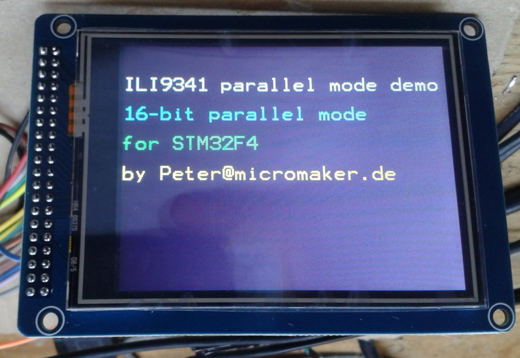
16-bit parallel mode
This mode is a little bit different. For our example we use the following ports in an STM32F411 controller:
//Parallel output (16 bit) line defines
#define LCDGPIO0 GPIOA //LSB (A7:A0)
#define LCDGPIO1 GPIOB //MSB (B7:B0)
#define LCD_RES 8 //Reset (active low) uses GPIOA
#define LCD_RD 9 //Write operation indicator (actice low) uses GPIOA
#define LCD_WR 10 //Read operation (actice low) uses GPIOA
#define LCD_RS 11 //CMD (low) or DATA (high) uses GPIOA
The function that writes data to the LCD then is:
//Parallel write data or command to LCD
void lcd_send(unsigned int dc, unsigned int val)
{
    LCDGPIO0->ODR |= (1 << LCD_RD); //RD high to write data

    if(!dc) //Cmd (0) or Data(1)?
    {
        LCDGPIO0->ODR &= ~(1 << LCD_RS); //Cmd=0
    }
    else
    {
        LCDGPIO0->ODR |= (1 << LCD_RS); //Data=1
    }

    LCDGPIO0->ODR &= ~0xFF; //LSB
    LCDGPIO0->ODR |= val & 0xFF;

    LCDGPIO1->ODR &= ~0xFF; //MSB
    LCDGPIO1->ODR |= (val >> 8) & 0xFF;

    LCDGPIO0->ODR &= ~(1 << LCD_WR);
    LCDGPIO0->ODR |= (1 << LCD_WR); //Transfer data
}
Transmitting one 16-bit integer also changes the function that draws one pixel:
void lcd_draw_pixel(unsigned int color)
{
    lcd_send(LCD_DATA, color);
}
So, as you can see the differences between 8- and 16-bitt parallel mode are minor bot nonetheless crucial.
A full code example has been stored on my Github repo.