
0 Abstract
A driver module for the very common ILI9341 LCD in SPI mode will be presented. Driver setup will be described as well as SPI bus configuration on the STM32F4 microcontroller.
1 ILI9341 colored LCD display
One of the very common colored LCD displays nowadays in use is the ILI9341 (datasheet). This LCD offers 320 by 240 pixel resolution, full color set (262k) and is driven by standard SPI control. The L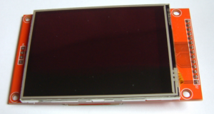 CD is available from Chinese vendors on a board also equipped with touchpad functionality. Most of these boards are 5V tolerant, but as the STM32 runs on 3.3V this is not a feature used here.
The control lines for SPI interface are:
//DC = PA2
//RES = PA3
//CS = PB12
//SCK = PB13
//MISO = PB14 (not used in this example)
//MOSI(SDI) = PB15
Explanation:
- DC: This pin defines if data or command is transmitted via the SPI bus. (0=command, 1=data)
- RES: The reset pin (active low)
- CS: chip select: (active low)
- SCK: clock signal on SPI bus
- MOSI/SDI: data signal on SPI bus
2 Timing diagram
With using the integrated SPI interface in the STM32F4 MCU reading and understanding this section is not crucial, we will refer to it either. According to data sheet the timing on the SPI lines is as following:
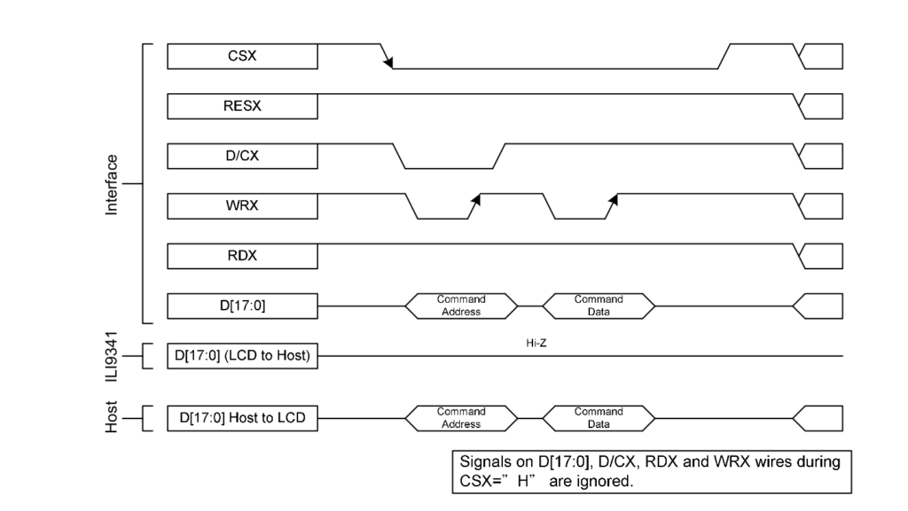
Understanding is not confusing (hopefully): CS is low when data is transferred, chip is selected. RES is hi always except when software starts. WRX is a “write signal” and can be kept low always when data reading is not intended. RDX is the corresponding read signal and must be kept high. Data is transmitted with MSB first.
3 Setting up STM32F4 SPI interface
For this project we want to use the integrated SPI functions in the STM32F4 MCU. The code sequence is as follows:
//////////////////////////////////////////
// Setup SPI
//////////////////////////////////////////
//PB12:CS; PB13:SCK; PB14:MISO; PB15:MOSI

RCC->AHB1ENR |= (1 << 0); //GPIOA clock enable
RCC->AHB1ENR |= (1 << 1); //GPIOB clock enable
RCC->APB1ENR |= (1 << 14); //Enable SPI2 clock, bit 14 in APB1ENR

//Non-AF ports for LCD
GPIOA->MODER |= (1 << (LCD_RES << 1)); //PA3 as output (Reset)
GPIOA->MODER |= (1 << (LCD_DC << 1)); //PA2 as output (DC)

//Alternate function ports
GPIOB->MODER &= ~(0b11111111U << (12 << 1)); //Reset bits 15:12
GPIOB->MODER |= (0b01 << (12 << 1)); //PB12 (CS) as output
GPIOB->MODER |= (0b101010U << (13 << 1)); //Set bits 15:13 to 0b101010 for alternate function (AF5)
GPIOB->OSPEEDR |= (0b11111111 << (12 << 1)); //Speed vy hi PB15:PB12

//Set AF5 (0x05) for SPI2 in AF registers (PB13:PB15)
GPIOB->AFR[1] |= (0x05 << (20)); //PB13
GPIOB->AFR[1] |= (0x05 << (24)); //PB14
GPIOB->AFR[1] |= (0x05 << (28)); //PB15

//Set SPI2 properties
SPI2->CR1 |= (1 << 2); //Master mode
SPI2->CR1 |= (1 << 9); //Software slave management enabled
SPI2->CR1 |= (1 << 8); //Internal slave select by software
SPI2->CR1 |= (1 << 6); //SPI2 enable
As SPI is part of the alternate function block in the MCU, please refer to sections Alternate functions and SPI in our tutorial. Other pins (RES and DC) are standard outputs ports, where no special technique is required. The last part of this code sections goes deeper int SPI setup. MCU is defined as master, slave settings are also defined and last SPI is enabled. A closer look into definition of SPI control register 1 (SPI_CR1) should make things clearer:
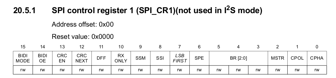
The NSS pins defines an extra pin for slave select. As set within in our example it is inactive and slave is selected by software.
4 Writing data to ILI9341 LCD via SPI
There is only one function that controls data transfer to the LCD:
void lcd_write(uint8_t cmd, uint8_t data)
{
    if(!cmd) //Cmd (0) or Data(1)?
    {
        LCDPORT &= ~(1 << LCD_DC); //Cmd=0
    }
    else
    {
        LCDPORT |= (1 << LCD_DC); //Data=1
    }

    GPIOB->ODR &= ~(1 << 12); //CS low
    SPI2->DR = data; //Write data to SPI interface
    while (!(SPI2->SR & (1 << 1))); //Wait till TX buf is clear
    GPIOB->ODR |= (1 << 12); //CS high
}
First operation is to submit if data (1) or command (0) is sent. Next SPI functions deliver data to the SPI bus. That’s all.
Also in the code is a set of graphical characters and functions to put out text, numbers on screen. As well as functions to draw lines that are very useful for drwaing boxes etc.
5 A General approach in designing LCD drivers
Usually when programming LCDs you start with setting/resetting a pixel:
void lcd_draw_pixel(int color)
{
    lcd_write(LCD_DATA, color >> 8);
    lcd_write(LCD_DATA, color & 0xFF);
}
After this has been accomplished, a function to write a charcter (based on the predfined character set) is established:
//Write character from font set to destination on screen
void lcd_putchar(int x, int y, int c, int size, int fcolor, int bcolor)
{
    int x0;
    int t0, t1, t2, t3, u;

    x0 = x;
    for(t0 = 0; t0 < FONTWIDTH * 2; t0 += 2)
    {
        for(t1 = 0; t1 < size; t1++)
        {
            u = xchar[c][t0 + 1] + (xchar[c][t0] << 8);
            lcd_set_xy(x0, y);
            for(t2 = 16; t2 >= 0; t2--)
            {
                if(u & (1 << t2))
                {
                    for(t3 = 0; t3 < size; t3++)
                    {
                        lcd_draw_pixel(fcolor);
                    }
                }
                else
                {
                    for(t3 = 0; t3 < size; t3++)
                    {
                        lcd_draw_pixel(bcolor);
                    }
                }
           }
           x0++;
        }
    }
}
After that you can put out strings to the screen:
//Print String to LCD
void lcd_putstring(int x, int y, char *text, int size, int fc, int bc)
{
    int t1 = 0, x0;

    x0 = x;
    while(text[t1])
    {
        lcd_putchar(x0, y, text[t1], size, fc, bc);
        x0 += (size * FONTWIDTH);
        t1++;
    }
}
To put out numbers, they have to be converted into a string first. 2 distinct functions are used.
//Convert a number to a string and print it
//col, row: Coordinates, Num: int or long to be displayed
//dec: Set position of decimal separator
//
//inv: Set to 1 if inverted charactor is required
void lcd_putnumber(int x, int y, long num, int dec, int lsize, int fc, int bc)
{
    char *s = (char*)malloc(16);
    if(s != NULL)
    {
        int2asc(num, dec, s, 16);
        lcd_putstring(x, y, s, lsize, fc, bc);
        free(s);
    }
    else
    {
        lcd_putstring(x, y, (char*)"Error", lsize, fc, bc);
    }
}


//////////////////////
// STRING FUNCTIONS //
//////////////////////
//INT 2 ASC
int int2asc(long num, int dec, char *buf, int buflen)
{
    int i, c, xp = 0, neg = 0;
    long n, dd = 1E09;

    if(!num)
    {
        *buf++ = '0';
        *buf = 0;
        return 1;
    }

    if(num < 0)
    {
        neg = 1;
        n = num * -1;
    }
    else
    {
        n = num;
    }

    //Fill buffer with \0
    for(i = 0; i < buflen; i++)
    {
        *(buf + i) = 0;
    }

    c = 9; //Max. number of displayable digits
    while(dd)
    {
        i = n / dd;
        n = n - i * dd;

        *(buf + 9 - c + xp) = i + 48;
        dd /= 10;
        if(c == dec && dec)
        {
            *(buf + 9 - c + ++xp) = '.';
        }
        c--;
    }

    //Search for 1st char different from '0'
    i = 0;
    while(*(buf + i) == 48)
    {
        *(buf + i++) = 32;
    }

    //Add minus-sign if neccessary
    if(neg)
    {
        *(buf + --i) = '-';
    }

    //Eleminate leading spaces
    c = 0;
    while(*(buf + i))
    {
        *(buf + c++) = *(buf + i++);
    }
    *(buf + c) = 0;

    return c;
}
The full code of this example is on my Github repo. CU!
by Peter Baier (DK7IH)